KNIFE BELT SANDER/BUFFER MODEL G1015 INSTRUCTION MANUAL COPYRIGHT © 1999 BY GRIZZLY INDUSTRIAL, INC. WARNING: NO PORTION OF THIS MANUAL MAY BE REPRODUCED IN ANY SHAPE OR FORM WITHOUT THE WRITTEN APPROVAL OF GRIZZLY INDUSTRIAL, INC. REVISED OCTOBER,1999. PRINTED IN U.S.A.
Table Of Contents 1. 2. 3. 4. 5. 6. 7. 8. PAGE SAFETY SAFETY RULES FOR ALL TOOLS ......................................................................3-4 ADDITIONAL SAFETY INSTRUCTIONS FOR SANDERS ......................................5 CIRCUIT REQUIREMENTS 110V OPERATION ....................................................................................................6 FUSING ....................................................................................................................
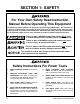
SECTION 1: SAFETY For Your Own Safety Read Instruction Manual Before Operating This Equipment The purpose of safety symbols is to attract your attention to possible dangers. This manual uses a series of symbols which are intended to convey the level of criticality of the safety message. The progression of symbols is described below. Remember that safety messages by themselves do not eliminate danger and are not a substitute for proper accident prevention measures.
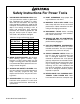
Safety Instructions For Power Tools 9. USE PROPER EXTENSION CORD. Make sure your extension cord is in good condition. Conductor size should be in accordance with the chart below. The amperage rating should be listed on the motor or tool nameplate. An undersized cord will cause a drop in line voltage resulting in loss of power and overheating. Your extension cord must also contain a ground wire and plug pin. Always repair or replace extension cords if they become damaged.
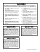
Additional Safety Instructions For Sanders 1. BE AWARE OF BELT or drum rotation when sanding. 2. KEEP FINGERTIPS AWAY from the moving belt or drum. Serious injury could result if skin contacts abrasives or moving parts. 3. NEVER USE EXCESSIVE FORCE when sanding. Doing this greatly increases the chances of personal injury and motor overload. 4. ALWAYS FEED THE WORK against the direction of rotation. 5.
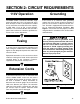
SECTION 2: CIRCUIT REQUIREMENTS 110V Operation Grounding The Model G1015 is wired for 110/120V, single phase operation only. The 1-HP motor will safely draw 10 amps at 110V. If you operate this sander on any circuit that is already close to its capacity, it might blow a fuse or trip a circuit breaker. However, if an unusual load does not exist and a power failure still occurs, contact a qualified electrician or our service department.
SECTION 3: INTRODUCTION Commentary We are proud to offer the Grizzly Model G1015 Knife Belt Sander/Buffer. The Model G1015 is part of a growing Grizzly family of fine woodworking and metalworking machinery. When used according to the guidelines set forth in this manual, you can expect years of trouble-free, enjoyable operation and proof of Grizzly’s commitment to customer satisfaction.
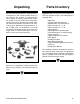
Unpacking Parts Inventory This Knife Belt Sander/Buffer is shipped from the manufacturer in two carefully packed cartons. If you discover the machine is damaged after you’ve signed for delivery, and the truck and driver are gone, you will need to file a freight claim with the carrier. Save the containers and all packing materials for possible inspection by the carrier or its agent. Without the packing materials, filing a freight claim can be difficult.
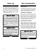
Clean Up Unpainted machine surfaces may be coated with a waxy oil to protect it from corrosion during shipment. Remove this protective coating with a solvent cleaner or citrus-based degreaser. Avoid chlorine-based solvents as they may damage painted surfaces should they come in contact. Always follow the usage instructions on the product you choose for clean up. Many of the solvents commonly used to clean machinery can be highly flammable, and toxic when inhaled or ingested.
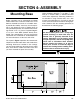
SECTION 4: ASSEMBLY Mounting Base Before assembly can be completed, the Model G1015 motor base and belt sander base must both be mounted to a bench, or a wooden base, to provide the stability necessary for safe operation. If you choose to create a wooden base for more portable operation, we recommend laminating two 20" x 12" x 3⁄4" pieces of plywood together, or use 1'' thick MDF (medium density fiberboard).
Motor Flat Edge Place the motor over its mounting holes as shown in Figure 4 and secure with 5⁄16" machine bolts or 5⁄16" lag bolts. Figure 5. Mounting spacer to end bell. Figure 4. Motor secured to base. Pivot Arm 1. Secure the round mounting spacer to the end bell of the motor using three (3) 1⁄4 - 20 x 1⁄2'' cap screws. See Figure 5. Make sure the cap screws go into the countersunk side of the spacer plate.
3. Tighten the three (3) 5⁄16" - 18 x 1" cap screws which hold the pivot arm bracket to the mounting bracket. Make sure this assembly is pushed far enough back that the bottom of the pivot arm bracket is approximately parallel to the base. 4. The mounting bracket can now be attached to the base or benchtop. Drill holes for the bracket using the four holes in the bracket as a guide (if you did not already pre-drill these holes). Secure with 5⁄16" machine bolts or 5⁄16" lag bolts.
Upper Arm Assembly To attach the upper sanding arm assembly: 1. Make certain the two (2) setscrews on the bottom of the pivot arm are firmly tightened. When the additional weight of the upper arm assembly is added, you do not want the pivot arm to flop over. 2. Remove the two (2) hand knobs from the pivot arm and slide the upper sanding arm assembly into the lower pivot arm. The sanding arm should seat on the collar. 3. Align the holes and replace the hand knobs and tighten. See Figure 9.
Belt Installation To install or replace the sanding belt: 1. If you are using a different length belt than the one supplied (72'') you will need to adjust the distance between the two wheels. See Section 5: Adjustments, Belt Tension for more detail. 2. Locate a position where the belt fits snugly over both the upper and lower drive wheels. Tool Rest The tool rest provides secure, angle-adjustable support for your workpiece while sanding. To install the tool rest: 1.
SECTION 5: Adjustments Belt Tension The Model G1015 features a self-tensioning mechanism which automatically applies tension to the sanding belt. If you are using a different length belt than the one supplied (72'') you will need to adjust the distance between the two wheels. To adjust the tensioning: 3. Replace the sanding belt onto the wheels and inspect for tension. Be sure the tracking adjustment is set so the upper wheel shaft is almost perpendicular.
Belt Tracking Proper angulation between the upper and lower drive wheels will result in a sanding belt which remains centered during operation. To adjust for proper tracking: 1. Turn the drive wheel several revolutions by hand. If the belt begins to shift from its center position to the right or left, tracking adjustment will be needed. Be careful when adjusting to make sure the belt does not run off the lower drive wheel and hit the mounting bracket. The edge of the sanding belt can be easily damaged. 2.
SECTION 6: Operations Test Run Belt Sanding Before you put your Belt Sander/Buffer into use, give it a quick inspection. Before inspecting, ensure that the machine is switched off and disconnected from its power source. The sanding belt can be used to sand wood or metal. We recommend aluminum oxide sanding belts for wood and silicon carbide for metal. Always be sure the belt is properly installed so the direction of rotation arrows follow the direction of rotation of the drive wheel.
The belt can also be used for knife grinding and sharpening. Figure 17 depicts a typical knife edge grinding operation. Generally this will be done with the tool rest removed. The sanding arm can also be tilted to a horizontal position if desired. See Figure 19. This can be more convenient for certain types of sanding or polishing operations. Make sure the arm is secured in the horizontal position with the two setscrews on the bottom of the pivot arm.
Buffing & Polishing 5. If facing the front of the machine, buffing and polishing should be done on the bottom of the wheel. See Figure 21. For buffing and polishing, Grizzly offers a broad selection of buffing wheels and polishing compounds that are very well suited for use with the Model G1015. Please refer to our current catalog. The auxiliary motor shaft arbor accepts buffing wheels with a 5/8'' bore. See Figure 20. Figure 21. Buffing on the bottom of the wheel. Figure 20.
Drum Sanding To sand using the optional pneumatic sanding drum: 1. Slide the optional sanding drum onto the shaft so the valve end is near the end of the shaft. Secure with the shaft nut provided. It is not necessary to use wheel flanges with the drum. See Figure 22. Figure 23. Recommended sleeve overlap. Figure 22 Sanding drum attached. 2. Ensure that the nut seats into the sanding drum. Tighten the nut while holding the sanding drum or the belt drive wheel.
SECTION 7: MAINTENANCE General Belts and Drums Make a habit of inspecting your sander each time you use it. Check for the following conditions and repair or replace when necessary. The sanding belt supplied with your G1015 is a 100 grit aluminum oxide belt suitable for general purpose wood sanding. Other applications, such as metal sanding and polishing will require different types of belts, both in composition and in grit.
SECTION 8: CLOSURE The following pages contain general machine data, parts diagrams/lists, troubleshooting guide and Warranty/Return information for your Model G1015 Knife Belt Sander/Buffer. If you need parts or help in assembling your machine, or if you need operational information, we encourage you to call our Service Department. Our trained service technicians will be glad to help you.
TROUBLESHOOTING - MOTOR SYMPTOM POSSIBLE CAUSE Motor will not start. 1. 2. Low voltage. 1. Open circuit in motor or 2. loose connections. Check power line for proper voltage. Inspect all lead connections on motor for loose or open connections. Motor will not start; 1. fuses or circuit break2. ers blow. Short circuit in line cord 1. or plug. Short circuit in motor or 2. loose connections. Incorrect fuses or circuit 3. breakers in power line.
TROUBLESHOOTING - OTHER SYMPTOM POSSIBLE CAUSE Abrasive belt runs off Not tracking properly. top wheel. CORRECTIVE ACTION 1. 2. 3. 4. Belt breaking or tear- 1. ing prematurely. 2. 3. Belt makes grinding 1. noise when started. 2. 3. 4. Pivot arm will not 1. rotate to horizontal. 2. Adjust upper wheel with tracking knob. Make sure upper wheel is aligned with drive wheel. Sanding shoe may be interfering. Adjust so it is square to the belt. Bevel the outer edges of the drive wheel slightly.
WARRANTY AND RETURNS Grizzly Industrial, Inc. warrants every product it sells for a period of 1 year to the original purchaser from the date of purchase. This warranty does not apply to defects due directly or indirectly to misuse, abuse, negligence, accidents, repairs or alterations or lack of maintenance.