5" PLANER MODEL G1021 INSTRUCTION MANUAL COPYRIGHT © 1986 BY GRIZZLY INDUSTRIAL, INC. REG.# TX 3 170 572 WARNING: NO PORTION OF THIS MANUAL MAY BE REPRODUCED IN ANY SHAPE OR FORM WITHOUT THE WRITTEN APPROVAL OF GRIZZLY INDUSTRIAL, INC. REVISED FEBRUARY, 1999. PRINTED IN U.S.
Table Of Contents 1. 2. 3. 4. 5. PAGE SAFETY ..........................................................................................................................3 SAFETY SYMBOLS ..................................................................................................3 SAFETY INSTRUCTIONS FOR POWER TOOLS ................................................3-4 ADDITIONAL SAFETY INSTRUCTIONS FOR PLANERS........................................5 CIRCUIT REQUIREMENTS .............................
Table Of Contents 6. 7. 8. -4- PAGE OPERATIONS ..............................................................................................................27 OVERVIEW..............................................................................................................27 TABLE LOCKS ........................................................................................................27 POWER FEED ................................................................................................
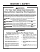
SECTION 1: SAFETY WARNING For Your Own Safety Read Instruction Manual Before Operating This Equipment The purpose of safety symbols is to attract your attention to possible dangers. This manual uses a series of symbols which are intended to convey the level of criticality of the safety message. The progression of symbols is described below. Remember that safety messages by themselves do not eliminate danger and are not a substitute for proper accident prevention measures.
WARNING Safety Instructions For Power Tools 9. USE PROPER EXTENSION CORD. Make sure your extension cord is in good condition. When using an extension cord, be sure it is rated Hard Service (grade S) or better. Conductor size must be 16 A.W.G. for cords up to 100 feet in length. An undersized cord will cause a drop in line voltage resulting in loss of power and overheating. Your extension cord must also contain a ground wire and plug pin. Always repair or replace extension cords if they become damaged.
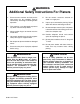
WARNING Additional Safety Instructions For Planers 1. 2. 3. Ensure that the machine sits firmly on the floor before use. Any “wobbles” must be corrected by shimming or blocking before operation. This machine is not designed to process any other material except wood. Never position fingers or thumbs near the infeed roller. 4. Long stock should always be fully supported by some type of support fixture. 5. Do not operate planer with dull or damaged knives. 6.
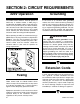
SECTION 2: CIRCUIT REQUIREMENTS 220V Operation Grounding The G1021 Planer motor is wired to operate at 220V only. A cordset without a 220V plug is included with the Model G1021. Plugs and receptacles can be purchased at your local hardware store or home center. When connecting to 220V, ensure that the electrical circuit is in fact a 220V circuit. Contact your local electrical contractor if uncertain about converting to 220V operation.
SECTION 3: INTRODUCTION Commentary Grizzly Industrial, Inc. is proud to offer the Model G1021 15" Planer. The G1021 is part of Grizzly’s growing family of fine woodworking and metalworking machinery. When used according to the guidelines stated in this manual, you can expect years of trouble-free, enjoyable operation. The Model G1021 is intended for home and professional use.
Unpacking The bandsaw is shipped from the factory in a carefully packed carton. If you find the machine to be damaged after you’ve signed for delivery and the truck and driver are already gone, you will need to file a freight claim with the carrier. Save the containers and all packing materials for inspection by the carrier or their agent. Without the packing materials, filing a freight claim can be difficult. If you need advice regarding this situation, please call us immediately.
Clean Up The unpainted surfaces are coated with a waxy oil to protect it from corrosion during shipment. Remove the protective coating with common paint thinner (mineral spirits) and paper towels. Do not use gasoline or other petroleum based solvents because of their extremely low flash points. Do not use chlorine-based solvents – if you happen to splash some onto a painted surface, you’ll ruin the finish. WARNING Follow the safety rules listed below when working with solvents. 1.
SECTION 4: ASSEMBLY Overview Most of your G1021 Planer has been assembled at the factory, but some parts must be assembled or installed after delivery. We have organized the assembly process into steps. Please follow along in the order presented here. TOOLS REQUIRED: Most of the tools required for assembly are included with the planer. However, you will also need a Phillips® and regular screwdriver as well as feeler gauge for adjustments later on. Figure 2. Stand crossbracing in place.
Planer Unit TO MOUNT THE PLANER: 1. Using the lifting handles shown in Figure 4, place the planer on the stand and align the four holes in the base over the four mounting holes in the stand. 2. Secure the planer base to the stand with the four hex bolts, nuts, washer and fender washers provided. CAUTION This planer is relatively heavy and awkward to handle. We strongly recommend that you get assistance. It will require at least two people to lift the planer onto the stand.
Handwheel Knife Setting Jig The handwheel is used to raise and lower the planer table. Each complete revolution raises the table 5⁄32" (4mm). The knife setting jig has been provided to make knife setting quick and easy. See Figure 7. TO ASSEMBLE THE KNIFE SETTING JIG: TO MOUNT THE HANDWHEEL: 1. Place the handwheel over the keyed shaft on the planer body. Make sure the key on the shaft and the keyway on the handwheel line up. The handwheel shaft is at the front right of the planer. See Figure 6. 2.
Extension Rollers Dust Port The extension rollers can be attached now, but it may be easier to make all the necessary adjustments to the planer before attaching them. The G1021 Planer features a 4" dust port for use with a dust collection system. TO ATTACH THE EXTENSION ROLLERS: 1. 2. Use the hex bolts and washers to mount the extension rollers. See Figure 8. Ensure that the top of the rollers are above the extension roller frame. Finger-tighten the mounting bolts for now.
SECTION 5: ADJUSTMENTS Overview A. The switch is thermally protected and magnetically controlled and features push buttons to turn the planer on and off. Once assembly has been completed, your G1021 15" Planer requires just a few adjustments to ready it for use in your shop. B. The handwheel raises and lowers the table and controls the depth of cut. Turning the handwheel clockwise raises the table and counter-clockwise lowers the table. C.
Gauge Block Table Adjustment Before attempting any table adjustments, you will need to construct a gauge block. See Figure 11. A larger gauge block diagram is also included at the end of the manual for your convenience. Precision adjustments later on require accuracy when milling the gauge block. Do not use common 2x4 material. Use maple or similar type of hardwood. Do not use the planer during the milling process since the gauge block is needed first to check and make planer adjustments.
If the gap difference from one side to the other is greater than 0.004", but less than 0.016", go to step 5. Knife Inspection If the gap difference from one side to the other is greater than 0.016", the table raising chain under the planer base will need to be adjusted. Please call our Customer Service number for chain adjustment instructions. The Model G1021 Planer has a three-knife cutterhead. The cutterhead is located in the head casting and rotates on two sealed bearings.
Knife Setting The process of setting the knives in the cutterhead will come into play whenever you sharpen or replace, or after determining that setting is necessary during the initial setup. The knives are locked into the cutterhead with wedge type gibs. Springs under each knife provide an upward pressure to help ease the setting process. Figure 14. Adjusting knife height. 4. If the knife bottoms out on the gauge block, repeat steps 1, 2 and 3, but start on the opposite side of the cutterhead. 5.
4. While holding the position of the knife setting jig, tighten the gib bolts down again in the cutterhead. Tighten the bolts evenly from the outside, working toward the middle. See Figure 16. 5. Repeat these steps for the other two knives. 3. Place the gauge block on the table directly under the cutterhead. Using a one millimeter (0.05") feeler gauge between the gauge block and the cutterhead, raise the table until one of the knives just touches the feeler gauge.
6. If an adjustment is necessary, loosen the locknuts and turn the setscrews. See Figure 18. Stop turning when the bottom of the chip breaker just touches the gauge block. 7. Re-tighten both locknuts 8. Replace the exhaust hood. Feed Roller Height The infeed and outfeed rollers propel the lumber through the planer. The rollers also press the lumber flat against the planer table. Set the infeed and outfeed rollers 0.040" below the knife edge at bottom dead center. TO CHECK ROLLER HEIGHT: Figure 18.
6. Repeat steps 1-5 for the opposite side of the roller. Repeat all steps for the outfeed roller. Feed Roller Pressure Feeler gauge measurement should equal 0.040". TO ADJUST ROLLER HEIGHT: 1. Remove the drive chain cover to access the roller adjustments on the drive chain side of the planer. A single socket head cap screw holds the drive chain cover on. Belt side adjustments are already accessible. 2.
4. Remove the springs that are in the holes left by the setscrews. See Figure 22. 5. Check for any dirt or grit. Clean the springs and setscrews if dirty. 6. Screw the three regular-pressure setscrews back in until they are flush with the top of the head casting. 7. TO ADJUST THE BED ROLLERS: 1. Ensure that power is disconnected and lay a high quality straightedge across both table rollers. Use a try square to keep the straightedge perpendicular to the table. 2.
3. Move the deflector until its edge is approximately 1⁄8" - 1⁄4" from the tip of the cutting knives. Push down on the deflector with a wooden stick to check if it will touch the knives. Cautiously rotate the cutterhead to ensure clearance. Do Not touch the knives severe cuts may result. 4. Re-tighten the chip deflector mounting bolts and re-mount the upper cover to the planer. Setscrews Setscrews Mounting Bolts Figure 24. Adjusting bed roller height.
Anti-Kickback Belts The Model G1021 Planer provides an anti-kickback safety feature. The anti-kickback fingers hang from a rod suspended across the front of the cutterhead casting. The anti-kickback fingers should be inspected regularly. Check the fingers to ensure that they swing freely and easily. See Figure 26. The belt and pulley assembly are on the left side of the planer. The belts transfer power from the motor to the cutterhead and then through the gearbox to the feed rollers.
TO CHECK BELT TENSION: Squeeze the V-Belts at their midpoints with moderate finger pressure. You should be able to deflect each V-Belt about 3/4". Belts will rarely be too tight, but will sometimes be too loose. To adjust belt tension: 1. Loosen the two bolts that hold the motor/pulley assembly to the planer. 2. Insert a wooden lever of suitable strength and pry the motor up to increase belt tension. See Figure 28. 3. Maintain lever position and check belt tension. Re-adjust if necessary. 4.
3. 4. The oil level in the gearbox should be to the bottom of the filler plug near the top of the gearbox. Top off with 80-90 wt. gear oil if necessary. Use 50 wt. motor oil if you are working in an unheated winter shop. See Figure 30. Drain and replace the oil yearly. See Figure 31. Extension Rollers N. EXTENSION ROLLERS If you elected to wait to install the extension rollers during the assembly process, install the extension rollers now. Refer to the Assembly Section.
Thickness Scale 4. Re-measure the board and compare your results with the scale. If there is a discrepancy, loosen the scale adjustment screw and correct the position. See Figure 33. The thickness scale, located below the handwheel, can be adjusted for accuracy. However, the machine must be operated to adjust the thickness scale. Follow the directions in the Operations Section for test running before attempting to make these adjustments. TO ADJUST THE SCALE: 1. 2. 3.
SECTION 6: Operations WARNING The Model G1021 15" Planer is a powerful woodworking machine, designed and constructed for professional-quality applications. Because of its powerful motor and razor-sharp knives, the Model G1021 is inherently dangerous and should be operated with considerable caution and respect. Failure to do so could result in damage to the machine, or severe injury to the operator or others in the work area.
Power Feed Handwheel The power feed features two feed rates; 16 FPM and 20 FPM. When running the machine, the operator can control the feed speed by moving the feed control knob. Moving the knob toward the machine produces the 20 FPM feed speed, away from the machine produces 16 FPM and a center position places the gear box in neutral. Figure 35. Crank the handwheel to raise or lower the table according to the desired workpiece thickness.
Test Run Wood Species Once the assembly is complete and the adjustments are done to your satisfaction, you are ready to test the machine. The species of wood, as well as its condition, have a dramatic effect on planing ability. The harder the wood (as illustrated by its shear strength), the more difficult it will be to plane. A brief listing of common hard and soft woods in relation to their shear strengths and planing difficulty is listed below.
Planing Difficulties The following descriptions of defects will give you some possible answers to problems you may encounter while planing different materials. Possible solutions follow the descriptions. Chipped Grain - usually a result of cutting against the grain, or planing wood with knots or excessive amount of cross grain. Chipped grain can also be caused by dull knives or misaligned chipbreaker. Often, chipped grain can be avoided by slowing down the feed rate and by taking shallow cuts.
SECTION 7: MAINTENANCE General Knives Make a habit of inspecting your planer each time you use it. Check for the following conditions and repair or replace when necessary. We recommend that dull knives be taken to a professional knife sharpener. Improperly sharpened knives can cause a number of defects to lumber and put unnecessary load on the motor and drive systems. If you can avoid sharpening knives yourself, allow them to be handled by a trained sharpener. 1. Loose mounting bolts. 2. Worn switch.
Lubrication The Model G1033 features factory-sealed bearings. A sealed bearing requires no lubrication during its lifetime. Should a bearing fail, your planer will probably develop a noticeable rumble, which will increase when the machine is put under load. If allowed to get worse, overheating of the journal containing the bad bearing could occur. If the bad bearing is not replaced, it will eventually seize - possibly doing damage to other parts of the machine.
Clean and lubricate the chain sprockets as needed. The gearbox oil should be checked before the first use. It is full when oil begins dribbling out of the fill hole. Oil should be replaced yearly. Use 80-90 Wt. gear oil in normal situations. Use 50 wt. motor oil for unheated, winter shops. See Adjustment Section. Lubrication Ports The lead screws and columns should be wiped of any grease and dust build up once a week. They should be relubricated with light machine oil. See Figure 42.
SECTION 8: CLOSURE The following pages contain parts diagrams, parts lists, general machine data and warranty/return information for your Model G1021 Planer. If you need parts or help in assembling your machine, or if you need operational information, we encourage you to call the Grizzly Industrial Service Department. Our trained service technicians will be glad to help you.
TROUBLESHOOTING This section covers the most common processing problems encountered in planing and what to do about them. Do not make any adjustments until planer is unplugged and moving parts have come to a complete stop. SYMPTOM POSSIBLE CAUSE Motor will not start. 1. 2. Low voltage. 1. Open circuit in motor or loose 2. connections. Check power line for proper voltage. Inspect all lead connections on motor for loose or open connections. Motor will not start; fuses or 1. circuit breakers blow. 2.
-38- 2 184 1 3 183 188 187 186 167 4 185 189 5 15 38 182 5 12 14 4 6 8 17 16 167A 7 18 14 13 19 90-1 15 90 90-1 153 152 176 87 36 21 20 19 88 23 91 92 94 87 88 168 159 28 175 2 177 161 156 155 154 2 97 192 151 174 160 2 25 27 30 31 31A 101 166 162 100 105 22 35 34 38 33 32 42 170 179 103 163 178 102 104 157 180 41 180 40 181 SEE PAGE 42-43 FOR REFERENCE NUMBER LISTING G1021 15" Planer
43 48 43 49 50 143 43 80 70 144 143 69 144 70 83 78 190 52 78 146 53 145 79 80 80 44 146 79 83 46 81 145 44 88 82 87 82A 51 44 45 89 87 64 63 88A 88 85 45 36 62 88A 36 63 62 55 55 57 75 76 73 57 65 73 68-1 68-2 55 73 66 67 68 75 76 77 57 75 76 G1021 15" Planer -39-
-40- 107 108 109 26 148 147 107 110 114 111 115 112 116A 121 117 114 114 116B 113 114 122 123 119 120 88 128 87 127 114 129 125 111 131 135 132 133 134 136 SEE PAGE 41-42 FOR REFERENCE NUMBER LISTING G1021 15" Planer
G1021 15" Planer 142 141 139 138 164 191 196 195 106 172 99 137 165A 138 140 139 194 193 150 139 173 138 149 SEE PAGE 41-42 FOR REFERENCE NUMBER LISTING -41-
Ref# Part# Description Ref# Part# Description 001 P1021001 PULLEY COVER 063 P1021063 LIFTING HANDLE 002 PFB01M FLANGE BOLT M6 - 1.0 x 12mm 064 P1021064 BASE 003 P1021003 V-BELT, SET OF 3 065 P1021065 IDLER BRACKET 004 PB07M HEX BOLT M8 - 1.25 x 25mm 066 P1021066 SHAFT 005 P1021005 SPECIAL WASHER 067 P1021067 IDLER SPROCKET 006 PB13M HEX BOLT M10 - 1.
Ref# Part# Description Ref# Part# Description 116B PK06M KEY 5 x 5 x 10mm 157 P1021157 CHIPBREAKER ADJUST ROD 117 P1021117 GEAR AND SHAFT 159 PR05M E-CLIP 15mm 119 P1021119 GEAR, 2 SPEED 160 P1021160 SPACER 120 P1021120 GEAR 161 P1021161 ANTI-KICKBACK FINGER 121 P1021121 DOUBLE GEAR 162 P1021162 SHAFT 122 P1021122 SHAFT 163 P1021163 INFEED ROLLER 123 PK11M KEY 6 x 6 x 40mm 164 P1021164 SPROCKET 124 PK21M KEY 5 x 5 x 23mm 165A P1021165A CHAIN, 31 LINKS 125 P
-44- G1021 15" Planer
WARRANTY AND RETURNS Grizzly Industrial, Inc. warrants every product it sells for a period of 1 year to the original purchaser from the date of purchase. This warranty does not apply to defects due directly or indirectly to misuse, abuse, negligence, accidents, repairs or alterations or lack of maintenance.