IMPORTS, INC. 3 /4 H.P. SHAPER MODEL G1024 INSTRUCTION MANUAL COPYRIGHT © 1994 BY GRIZZLY INDUSTRIAL, INC. WARNING: NO PORTION OF THIS MANUAL MAY BE REPRODUCED IN ANY SHAPE OR FORM WITHOUT THE WRITTEN APPROVAL OF GRIZZLY INDUSTRIAL, INC. REVISED JUNE, 1994. PRINTED IN USA DISCONTINUED MACHINE MANUAL DISCLAIMER THE INFORMATION IN THIS MANUAL REPRESENTS THE LAST CONFIGURATION OF THE MACHINE BEFORE IT WAS DISCONTINUED. MACHINE CONFIGURATIONS MAY HAVE CHANGED AS PRODUCT IMPROVEMENTS WERE INCORPORATED.
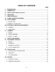
TABLE OF CONTENTS PAGE I. INTRODUCTION ..........................................................................................................1 II. COMMENTARY ..........................................................................................................1 III. SAFETY RULES FOR ALL TOOLS ............................................................................2 IV. UNPACKING ...............................................................................................................
I. INTRODUCTION We are proud to offer the Model G1024 Shaper. The Model G1024 is part of a growing Grizzly family of fine woodworking machinery. When used according to the guidelines set forth in this manual, you can expect years of trouble-free, enjoyable operation and proof of Grizzly’s commitment to customer satisfaction. The Model G1024 is intended for use in a home or small professional shop. This shaper features a 3 /4 H.P., 110 / 220V single phase motor and full reversing capabilities.
The information in this manual has been obtained from sources believed to be reliable and as up-todate as possible. While this manual is intended to be a substantial source of basic shaping information, it is by no means the last word on shaping. Instead, we have focused primarily on the proper assembly and adjustment of the machine – as well as some basic information on shaping procedures. We have also included some important safety measures which we believe to be essential to this machine’s operation.
. KEEP WORK AREA CLEAN. Cluttered areas and benches invite accidents. 6. AVOID DANGEROUS ENVIRONMENTS. Do not use power tools in damp or wet locations or expose them to rain. Keep your work area well lighted. 7. KEEP CHILDREN AND VISITORS AWAY. All children and visitors should be kept a safe distance away from your work area. 8. MAKE WORKSHOP CHILD-PROOF with padlocks, master switches, or by removing starter keys. 9. DO NOT FORCE TOOL.
22. NEVER LEAVE THE TOOL RUNNING UNATTENDED - TURN POWER OFF. Do not leave the tool until it comes to a full stop. 23. DRUGS, ALCOHOL, MEDICATION. Do not operate the tool under the influence of drugs, alcohol, or any medication. Never operate machinery when overly fatigued. IV. UNPACKING The Model G1024 Shaper is shipped from the factory in heavy-duty cardboard packaging. Carefully remove the cardboard box by cutting through the box at its base.
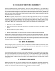
V. PIECE INVENTORY Take a quick inventory of the parts and put them aside for assembly later. Since the majority of the shaper is pre-assembled at the factory, there aren’t a lot of items to inventory. You should have the following: • • • • • • Shaper Unit Miter Gauge Spindle and Spacers Fence Boards Freehand Guard Bolt Bag (See below) • • Stand (4 pcs.) Adjustable Fence (3 pcs.) The Model G1026 Bolt Box contains: Rubber Feet Hex Bolt M6-1.0x12 Hex Nut M6-1.0 Flat Washer 3/8" Carriage Bolt M8-1.
VI. CLEAN-UP BEFORE ASSEMBLY All of the unpainted surfaces on this machine – and a few of the painted ones – are coated with a preservative oil, called Cosmolene, which prevents rust and corrosion during shipping. The coating can be removed with paint thinner (mineral spirits) and a good supply of paper towels, although you may find that careful scraping with a putty knife may be necessary where the coating is particularly thick.
VIII. ELECTRICAL SERVICE REQUIREMENTS The Grizzly Model G1024 Shaper is furnished with a complete electrical package: A 3450 RPM TEFC 3/4 H.P. motor, ON-OFF starter switch, FORWARD/REVERSE switch and a cord set. The motor is single phase and may be operated on 220/240V, as well as 110/120V. A. GENERAL The Model G1024 comes with a standard 110V cord and plug. Its motor draws 10 amps. While that is not excessive, using the Model G1024 on a circuit that is already close to capacity could result in overload.
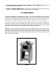
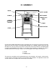
IX. ASSEMBLY FENCE SAFETY GUARD MITER GAUGE SPINDLE SPINDLE LOCK KNOB SPINDLE ELEVATION HOUSING TABLE ON/OFF SWITCH STAND Figure 3 Carefully lift the Model G1024 Shaper from its packaging. Be sure to get plenty of help when attempting to lift or move the machine. The Model G1024 Shaper has a shipping weight of more than 150 lbs. Make sure you have plenty of help when it comes time to move the machine.
A. STAND The Model G1024 Shaper features an A-frame stand. Begin assembling the stand by attaching the four rubber feet to the bottom of the side panels with the M6-1.0x12 hex bolts, M6-1.0 hex nuts and 3 /8" flat washers provided. See Figure 4. Figure 4 Figure 5 Once the rubber feet are connected, attach the crossbars loosely with the carriage bolts, nuts and washers provided. See Figure 5. At this point, the stand will be somewhat wobbly.
B. FENCE ASSEMBLY The Model G1024 Shaper comes with a two-piece adjustable fence. Before attaching the fence unit to the shaper table, you will want to “wood” it. The wood fence pieces included with the Model G1024 are pre-drilled and counterbored to allow the slotted mounting screws to rest below the wood surface once they are tightened. Most woodworkers like to replace the wood pieces on the fence with wider and thicker boards. This gives the user greater stability and a larger bearing surface.
C. SAFETY GUARD The Model G1024 features a clear acrylic safety guard which is designed to deflect wood chips away from the machine’s operator. To attach the guard, slip the support rod into the hole provided in the bracket bolted to the back of the shaper table. See Figure 7. The height of the safety guard can be adjusted by loosening the locking knob on the bracket and raising or lowering the support rod. Be sure to re-tighten the locking knob securely after making height adjustments.
X. SAFETY PROCEDURES This tool is capable of causing serious injury if used recklessly. This doesn’t mean that the machinery should be feared, but it does deserve a healthy respect for its power and potential danger. At the beginning of this manual we shared some general safety procedures with you. We want to reemphasize a few points we feel are critical to safe shaper operation: 1. GROUND EQUIPMENT PROPERLY. We can’t over-emphasize the importance of a well grounded machine. 2.
14. HAND SAFETY. Never pass your hands directly over, or in front of the cutter. As one hand approaches the 12-inch radius point, move it away from the cutter to the outfeed side and reposition the hand at least 12 inches beyond the cutter. 15. STOCK FEED. Always feed stock opposite the direction of the cutter rotation. For example, if the cutter rotation is counterclockwise, feed from right to left. NEVER back stock out of the cutter along the fence, once the cut has been started.
20. STOCK CONDITION. The danger of experiencing kick-back is increased when the stock has knots, holes, or foreign objects in it. Warped stock should be run through a jointer before attempting to run it through a shaper. 21. MISUSE. Do not use the Model G1024 for anything other than its intended purpose. If used for other purposes, Grizzly disclaims any real or implied warranty and is not responsible for any damage or injury which may result from that use. 22. USE the correct safety guards. 23.
XI. ADJUSTMENT SECTION Any adjustments or maintenance performed on the Model G1024 should be done with the power off, the plug disconnected from the power source and only after all moving parts have come to a complete stop. Make sure the machine is level and secure. The following are recommended steps for adjusting the shaper. Please read the following adjustment procedures to ensure the shaper is adjusted and ready for operation. This section covers adjustment procedures for the following items.
Workpiece Outfeed Fence Infeed Fence Cutter Rotation Feed Direction Improper Fence Adjustment Figure 11 When the shaping operation removes the entire face of the workpiece, the shaped surface will not be supported by the outfeed fence when the fences are paralleled, or mis-aligned, as shown in Figure 11. In this case, a test sample of the desired cut should be advanced to the point shown, then stopped.
Outfeed Fence Cutter Rotation Workpiece Infeed Fence TTER CU Feed Direction Figure 13 Take your time when adjusting the fence. Always use a piece of scrap wood to make a first run sample. Micro-adjust accordingly. Double check yourself to make sure all hold-down devices are secure. Remember to use appropriate guards when using the fence system. B.
C. SPINDLE ELEVATION The Model G1024 Shaper features a locking spindle which can be adjusted for up to 7/8" of vertical movement. To adjust the height of the spindle: 1. Loosen the locking knob on the right-hand side of the shaper. 2. Reaching under the shaper table, move the vertical adjustment lever right or left until the spindle reaches its desired height. See Figure 15. 3. Re-tighten the locking knob. 4.
XII. RUB COLLARS Rub collars are used when shaping curved or irregular workpieces, such as arched doors or round table tops. They also allow you to perform freehand work. There are two types of rub collars; solid and ball-bearing. Don’t confuse spacers with solid rub collars. Spacers aren’t always machined to close tolerances and not every ball-bearing can be used as a rub collar. Grizzly carries an extensive line of spacers and rub collars designed for use with Grizzly shapers.
B. EXAMPLES Rub collars may be used in any of the following positions: 1. Below the cutter. 2. Above the cutter. 3. Between two cutters. Suppose you want to mill a 3/8" x 1/2" rabbet. You must have a sufficient amount of uncut wood to provide adequate contact with the rub collar. Remember that the width of the rabbet is controlled by the diameter of the rub collar and the depth of the rabbet is controlled by the spindle height adjustment.
Rub collar above the cutter: Spindle Spindle Nut Workpiece Safety Washer Rub Collar Cutter Table Table Spindle Assembly Figure 18 When the collar is used above the cutter, as shown in Figure 18, the cut cannot be seen. Yet, this offers some advantage in that the cut is not affected by slight variations in the stock. Also, accidental lifting will not damage the workpiece. Simply correct the mistake by repeating the operation.
C. PATTERN WORK When using a pattern, the rub collar can be positioned either above, below, or in-between cutters. See Figure 20. The pattern is usually used when the entire edge is to be shaped or when many duplicate pieces are needed. Pattern work is particularly useful when rough cutting irregular shapes oversize and then shaping the edge in a simple two-step operation. A pattern can be incorporated into a fixture by way of adding toggle clamps, hand holds, or other safety devices.
5. Position the fences for your desired depth of cut. See the fence adjustment section for details. 6. Use a hold-down, or other safety device. See Figures 21 and 22. 7. Make a sample cut on a scrap piece of wood to check your adjustments. 8. If everything is correct, run your stock through the shaper using your left hand to support the workpiece against the fence and your right to feed (if the rotation is counterclockwise). Switch hands for clockwise rotation. 9.
B. IRREGULAR SHAPING Irregular or freehand shaping takes a high degree of skill and dexterity. This is where the real application of the shaper comes into focus. The fence assembly is not used in irregular shaping, so rub collars must be used. Choose the correct diameter for the appropriate depth of cut. See the rub collar section for details. CAUTION: Freehand work is one of the most dangerous operations done on a shaper. When doing freehand work a starting pin must be used.
5. Insert a starting pin into the table surface, using the pin location that best supports your work. 6. Inspect your stock or pattern for any irregularities that might transfer to the cut. 7. Use some type of hold-down fixture and guard when doing freehand work. See Figure 24. Figure 24 8. Make a sample cut on a piece of scrap wood. 9. If everything is correct, feed your workpiece along the cutter, using firm pressure to keep your work against the rub collar. Feed against the cutter rotation only.
When making a pattern, jig, or fixture, here are a few things to consider: 1. Use a material that will smoothly follow the rub collar or fence. 2. Make the fixture stable. Use proven methods and materials. 3. Fasten hand holds for operator comfort and safety. 4. Secure your workpiece on three sides with toggle clamps or fasten the workpiece to the fixture with wood screws. Make sure they do not protrude through the workpiece. 5.
XIV. EQUIPMENT MAINTENANCE Your Model G1024 Shaper requires very little maintenance. A thorough cleaning, now and again, will increase the machine’s durability and efficiency, by removing dust and grime that can gum up moving parts. Sharp cutting surfaces are essential for top performance. If you find that the machine cuts less efficiently than usual, inspect the cutters and repair or replace them as necessary.
XVI. MACHINE DATA GRIZZLY MODEL G1024 3/4 H.P. SHAPER Design Type ....................................................................................................................Floor Model Overall Dimensions: Table ................................................................................................................................15” x 18” Height From Floor to Top of Fence ..........................................................................................
XVII. WARRANTY AND RETURNS LIMITED WARRANTY Grizzly Industrial, Inc. warrants every product it sells for a period of one year on all parts and one year on all electric motors to the original purchaser from the date of purchase. This warranty does not apply to defects due directly or indirectly to misuse, abuse, negligence, accidents, repairs or alterations or lack of maintenance.
XVIII. PARTS LISTS AND DIAGRAMS A.
B. MODEL G1024 SHAPER PARTS LIST Ref. # Part # Description Ref. # Part # Description 001 P1022003 Side Panel 037 P1024037 Coil Spring 002 P1024002 Tie Bar 038 P1024038 Spring Collar 003 PB02M Hex Bolt M6-1.0x12 039 P1024039 Lock Handle 004 P1024004 Rubber Foot 040 PW06 Flat Washer 1/4" 005 PW02 Flat Washer 3/8" 041 PS14M Phil Hd Screw M6-1.0x12 006 PN01M Hex Nut M6-1.0 042 P1024042 Half Collar 007 PW02 Flat Washer 3/8" 043 PSB26M Cap Screw M6-1.
B. MODEL G1024 SHAPER PARTS LIST (CONTINUED) Ref. # Part # 075 P1026223 Description Safety Washer Ref. # Part # 097 PVA30 Description V-belt A-30 076 P1024076 Cutter Spindle 098 P1024098 Motor Pulley 077 P1024077 Bearing Cover 099 PSS04M Setscrew M6-1.0x12 078 P1024078 Spindle Cartridge 100 P1024100 Motor 079 P1024079 Steel Ball 101 P1024101 Carriage Bolt 080 PR23M Retaining Ring 40mm 102 PW02 Flat Washer 3/8" 081 P6203 Ball Bearing 103 PN03M Hex Nut M8-1.
XIX. USING THE MODEL G1793 ROUTER BIT SPINDLE The Model G1793 Router Bit Spindle is a handy accessory available for your Model G1024 shaper, which allows you to use your standard router bits as shaper cutters. Using the optional router bit spindle does require some minor modifications to the Model G1024. To maximize the effectiveness of the router spindle, it is necessary to build a false table to increase the height of the shaper table by 11/2". To make a false table: 1.