MODEL G0548ZP G1028Z2/G1029Z2/G1029Z2P DUST COLLECTOR OWNER'S Manual (For models manufactured since 12/12) 247570 G0548ZP G1028Z2/G1029Z2 Copyright © FEBRUARY, 2012 By Grizzly Industrial, Inc. revised december, 2012 (BL) Warning: No portion of this manual may be reproduced in any shape Or form without the written approval of Grizzly Industrial, inc.
This manual provides critical safety instructions on the proper setup, operation, maintenance, and service of this machine/tool. Save this document, refer to it often, and use it to instruct other operators. Failure to read, understand and follow the instructions in this manual may result in fire or serious personal injury—including amputation, electrocution, or death. The owner of this machine/tool is solely responsible for its safe use.
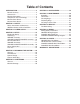
Table of Contents INTRODUCTION................................................ 2 Manual Accuracy............................................ 2 Contact Info.................................................... 2 Machine Description....................................... 2 Components and Terminology........................ 3 Machine Data Sheets..................................... 4 Machine Data Sheets..................................... 4 SECTION 1: SAFETY........................................
INTRODUCTION Manual Accuracy Contact Info LZ VgZ egdjY id d[[Zg i]^h bVcjVa l^i] ndjg cZl bVX]^cZ LZ kZ bVYZ ZkZgn Z[[dgi id WZ ZmVXi l^i] i]Z ^chigjXi^dch! heZX^[^XVi^dch! YgVl^c\h! VcY e]did\gVe]h d[ i]Z bVX]^cZ lZ jhZY l]Zc lg^i^c\ i]^h bVcjVa# =dlZkZg! hdbZi^bZh lZ hi^aa bV`Z Vc dXXVh^dcVa b^hiV`Z# LZ hiVcY WZ]^cY djg bVX]^cZh# >[ ndj ]VkZ Vcn fjZhi^dch dg cZZY ]Zae! jhZ i]Z ^c[dgbVi^dc WZadl id XdciVXi jh# 7Z[dgZ XdciVXi^c\! eaZVhZ \Zi i]Z hZg^Va cjbWZg V
Components and Terminology Canister Filter G1028Z2, G1029Z2/Z2P G0548ZP Filter Cleaning Handle Filter Bag Outlet Connector Hose Outlet Connector Collector Collection Bag 3-Port Inlet Connector Caster 2-Port Inlet Connector Motor ON/OFF Paddle Switch To reduce the risk of serious injury when using this machine, read and understand this entire manual before beginning any operations. Figure 1. Rear view identification. G0548ZP, G1028Z2, G1029Z2-Z2P (Mfg.
MODEL G0548ZP, G1028Z2, G1029Z2, G1029Z2P DUST COLLECTORS Model Number G0548ZP G1028Z2 G1029Z2/G1029Z2P Product Dimensions Weight Width (side-to-side)/Depth (frontto-back)/Height 145 lbs. 95 lbs. 37 x 27 x 71 in. 37 x 27 x 76 in. Foot Print (Width/Depth) 33-1/2 x 21-1/4 in. Shipping Dimensions Carton 1 Type Cardboard Content Weight Width (side-to-side)/Depth (frontto-back)/Height Machine 126 lbs. 118 lbs. 126 lbs. 36 x 23 x 23 in. 35 x 23 x 23 in. 36 x 23 x 22 in.
Model Number G0548ZP G1028Z2 G1029Z2/G1029Z2P Main Motor Type TEFC Capacitor Start Induction Horsepower 2 HP 1.5 HP 2 HP Voltage 240V 120V/240V 240V Phase Amps Single-Phase 9A 12A/6A Speed 3450 RPM Cycle 60 Hz Power Transfer 9A Direct Drive Bearings Shielded & Permanently Lubricated Operation Information Type Air Suction Capacity Maximum Static Pressure Canister Bag 1700 CFM 1300 CFM 1550 CFM 10 in. 9 in. 11 in. Main Inlet Size 6 in.
Model Number G0548ZP G1028Z2 G1029Z2/G1029Z2P Construction Base Frame Fabricated Sheet Metal with Casters Fabricated Sheet Metal Caster Formed Steel High Density Plastic Paint Powder Coated Other Specifications Height with Bags Inflated 71 in. 78 in.
SECTION 1: SAFETY For Your Own Safety, Read Instruction Manual Before Operating this Machine The purpose of safety symbols is to attract your attention to possible hazardous conditions. This manual uses a series of symbols and signal words intended to convey the level of importance of the safety messages. The progression of symbols is described below. Remember that safety messages by themselves do not eliminate danger and are not a substitute for proper accident prevention measures.
WEARING PROPER APPAREL. 9d cdi lZVg Xadi]^c\! VeeVgZa dg _ZlZagn i]Vi XVc WZXdbZ ZciVc\aZY ^c bdk^c\ eVgih# 6alVnh i^Z WVX` dg XdkZg adc\ ]V^g# LZVg cdc"ha^e [ddilZVg id Vkd^Y VXX^YZciVa ha^eh! l]^X] XdjaY XVjhZ adhh d[ ldg`" e^ZXZ Xdcigda# HAZARDOUS DUST.
Additional Safety for Dust Collectors intended use. this dust collector is designed for collecting wood dust and chips from woodworking machines. do not use it to collect metal, dirt, drywall, asbestos, lead paint, silica, liquids, aerosols, biohazards, or explosive materials. Collecting the wrong materials can result in serious inhalation hazards, fire, or machine damage. hazardous dust. dust created while using machinery may cause cancer, birth defects, or long-term respiratory damage.
SECTION 2: POWER SUPPLY Availability Circuit Information 7Z[dgZ ^chiVaa^c\ i]Z bVX]^cZ! Xdch^YZg i]Z VkV^a" VW^a^in VcY egdm^b^in d[ i]Z gZfj^gZY edlZg hjeean X^gXj^i# >[ Vc Zm^hi^c\ X^gXj^i YdZh cdi bZZi i]Z gZfj^gZbZcih [dg i]^h bVX]^cZ! V cZl X^gXj^i bjhi WZ ^chiVaaZY# Id b^c^b^oZ i]Z g^h` d[ ZaZXigdXji^dc! [^gZ! dg Zfj^ebZci YVbV\Z! ^chiVaaVi^dc ldg` VcY ZaZXig^XVa l^g^c\ bjhi WZ YdcZ Wn Vc ZaZXig^XVc dg fjVa^[^ZY hZgk^XZ eZghdccZa ^c VXXdgYVcXZ l^i] Vaa Veea^XVWaZ XdYZh VcY hiVc
G1028Z2 Circuit Requirements for 120V Operation (Prewired) Serious injury could occur if you connect the machine to power before completing the setup process. DO NOT connect to power until instructed later in this manual. Circuit Requirements for G0548ZP/ G1029Z2/G1029Z2P Nominal Voltage.........................................240V Cycle...........................................................60 Hz Phase............................................ Single-Phase Circuit Rating..............................
G1028Z2 Circuit Requirements for 240V Operation I]^h bVX]^cZ XVc WZ XdckZgiZY id deZgViZ dc V ')%K edlZg hjeean gZ[Zg id Voltage Conversion ^chigjXi^dch i]Vi ]Vh V kZg^[^ZY \gdjcY VcY bZZih i]Z [daadl^c\ gZfj^gZbZcih/ Nominal Voltage.........................................240V Cycle...........................................................60 Hz Phase............................................ Single-Phase Circuit Rating....................................... 15 Amps Plug/Receptacle..........
4. The voltage conversion MUST be performed by an electrician or qualified service personnel. 240 VOLT (REWIRED) The voltage conversion procedure consists of rewiring the motor and installing the correct plug. A wiring diagram is provided on Page 42 for your reference. Gjc 8VeVX^idg )*B;9 '*%K68 IMPORTANT: If the diagram included on the motor conflicts with the one on Page 42, the motor may have changed since the manual was printed. Use the diagram included on the motor junction box cover instead.
SECTION 3: SETUP Needed for Setup This machine presents serious injury hazards to untrained users. Read through this entire manual to become familiar with the controls and operations before starting the machine! Wear safety glasses during the entire setup process! This machine and its components are very heavy. Get lifting help or use power lifting equipment such as a forklift to move heavy items.
G0548ZP Inventory I]Z [daadl^c\ ^h V YZhXg^ei^dc d[ i]Z bV^c Xdbed" cZcih h]^eeZY l^i] ndjg bVX]^cZ# AVn i]Z Xdbed" cZcih dji id ^ckZcidgn i]Zb# Box 2: (Figure 8) Qty J. Canister Filter.............................................. 1 K. Foam Adhesive Bag.................................... 1 —Wide Foam Strip 5 x 42mm..................... 1 — Narrow Foam Strip 6 x 20mm................. 1 L. Canister Belt Clamp.................................... 1 M. Canister Cleaning Handle...........................
G1028Z2/G1029Z2/ G1029Z2P Inventory I]Z [daadl^c\ ^h V YZhXg^ei^dc d[ i]Z bV^c Xdbed" cZcih h]^eeZY l^i] ndjg bVX]^cZ# AVn i]Z Xdbed" cZcih dji id ^ckZcidgn i]Zb# A C B D >[ Vcn cdc"egdeg^ZiVgn eVgih VgZ b^hh^c\ Z#\# V cji dg V lVh]Zg ! lZ l^aa \aVYan gZeaVXZ i]Zb0 dg [dg i]Z hV`Z d[ ZmeZY^ZcXn! gZeaVXZbZcih XVc WZ dWiV^cZY Vi ndjg adXVa ]VgYlVgZ hidgZ# Box Components: Qty A. Motor & Impeller Assembly......................... 1 B. Collector Body Assembly............................
Site Considerations G0548ZP Assembly To assemble your dust collector: Floor Load Refer to the Machine Data Sheet for the weight and footprint specifications of your machine. Some residential floors may require additional reinforcement to support both the machine and operator. 1. Place the base upside down on a flat, protected surface. 2. Attach the casters to the base with (16) 5⁄16-18 x 1⁄2" flange bolts, as shown in Figure 11.
4. Place a rubber gasket around the impeller outlet rim, as shown in Figure 13. 6. Align the canister support with the mounting holes on the base, as shown in Figure 15, then secure it in place with (2) 5⁄16-18 x 1⁄2" flange bolts. Gasket Canister Support x2 Figure 13. Positioning impeller outlet gasket. 5. Secure the outlet connector to the impeller outlet with (8) 5⁄16-18 x 1⁄2" flange bolts, as shown in Figure 14. Outlet Connector Figure 15. Canister support installed. 7.
9. Apply the 5 x 42mm wide foam strip to the outside top of the collector, as shown in Figure 17, and trim the excess so that the ends of the strip come together evenly, as shown in Figure 18. 5 x 42mm Foam Strip 10. Place the cleaning handle on the canister shaft, align the hex bolt with the flat portion of the shaft and tighten the bolt, as shown in Figure 19. Hex Bolt Canister Shaft Flat Figure 17. Applying the wide foam strip to the collector. Ends Matched Evenly Figure 19.
12. Apply the 6 x 20mm foam strip to the bottom of the collector, then trim the excess and evenly match the ends (see Figure 20). 13. Attach a collection bag to the hooks around the bottom of the collector, then tighten the collection bag clamp around the foam strip to hold the bag in place, as shown in Figure 21. G1028Z2/G1029Z2/ G1029Z2P Assembly To assemble your machine: 1. Mount the casters to the base plate using (16) 5⁄16"-18 x 1⁄2" flange bolts, as shown in Figure 23.
3. Insert the rubber gasket between the collector and outlet flange, and secure the flange with (8) 5⁄16"-18 x 1⁄2" flange bolts, as shown in Figure 25. Note: When connecting parts that have a gasket applied to the mounting surface, always tighten the fasteners in a crisscross manner to ensure the gasket does not become crimped and the seal compromised. 5. Secure the front lower support bracket to the collector with (2) 5⁄16"-18 x 1⁄2" flange bolts. 6.
7. Slip a loosened hose clamp over each end of the flex-hose, and position the hose ends over the outlets, as shown in Figure 29. Tighten each hose clamp until snug. Ends Matched Evenly Flex Hose Hose Clamps Figure 31. Example of wide foam strip ends matched evenly. 9. Hook the upper filter bag (fabric) on the support bracket, as shown in Figure 32. Figure 29. Attaching flex hose onto collector body outlet. 8.
Power Connection 11. Apply the 6 x 20 foam strip to the bottom of the collector, then trim the excess and evenly match the ends (see Figure 34). After you have completed all previous setup instructions and circuit requirements, the machine is ready to be connected to the power supply. 6 x 20 Foam Strip Figure 34. Example of 6 x 20 foam strip installed. 12.
Test Run 6. Remove the switch disabling key, as shown in Figure 39. Once the assembly is complete, test run your machine to make sure it runs properly and is ready for regular operation. The test run consists of verifying the following: 1) The motor powers up and runs correctly, and 2) the safety disabling mechanism on the switch works correctly.
SECTION 4: DESIGNING THE SYSTEM General Always guard against static electrical build up by grounding all dust collection lines. This dust collector can be operated as either a stationary, central dust collector or a mobile unit. There are advantages and disadvantages to both setups. The advantage of the mobile system is eliminating the cost of many ducts and fittings. On the other hand, the stationary system is more efficient and customizable.
Metal Duct Flexible Duct Advantages of metal duct is its conductivity, efficiency, and that it does not contribute to static electrical charge build-up. however, static charges are still produced when dust particles strike other dust particles as they move through the duct. since metal duct is a conductor, it can be grounded quite easily to dissipate any static electrical charges. Flexible hose is generally used for short runs, small shops and at rigid duct-to-tool connections.
System Design Decide Who Will Design For most small-to-medium sized shops, you can design and build the dust collection system yourself without hiring engineers or consultants. We have included some basic information here to get you started on a basic design. if you have a large shop or plan to design a complicated system, we recommend doing additional research beyond this manual or seeking the help of an expert.
3. directional changes should be kept to a minimum. the more directional change fittings you use directly increases the overall resistance to airflow. 4. gradual directional changes are more efficient than sudden directional changes (i.e. use the largest corner radius possible when changing hose or pipe direction). 5. Each individual branch line should have a blast gate immediately after the branch to control suction from one machine to another. 6.
Determining Main Line Duct Size the general rule of thumb for a main line duct is that the velocity of the airflow must not fall below 3500 Fpm. For small/medium sized shops, using the inlet size of the dust collector as the main line duct size will usually keep the air velocity above 3500 Fpm and, depending on your system, will allow you to keep multiple branches open at one time. mark your drawing, as shown in the figure below, but using the inlet size for your dust collector as the main line.
Planning Drop Downs duct dia. approximate static pressure loss per foot of rigid pipe approximate static pressure loss per foot of flex pipe main lines at 3500 Fpm Branch lines at 4000 Fpm main Branch lines lines at 3500 at 4000 Fpm Fpm 2" 0.091 0.122 0.35 0.453 2.5" 0.08 0.107 0.306 0.397 3" 0.071 0.094 0.271 0.352 4" 0.057 0.075 0.215 0.28 5" 0.046 0.059 0.172 0.225 6" 0.037 0.047 0.136 0.18 Id EaVcZg 7" 0.029 0.036 0.106 0.141 Figure 52. Drop down setup. 8" 0.
3. Add the additional factors from the followingtable to your list. additional factors seasoned (well used) dust Collection Filter Entry loss at large machine hood static pressure 1" 2" Figure 54. Additional factors affecting static pressure. 4. total your list as shown in the example below to come up with your overall static pressure loss number for that line. note: Always account for a seasoned filter, so you don't end up with a system that only works right when the filter is clean.
System Grounding since plastic hose is abundant, relatively inexpensive, easily assembled and air tight, it is a very popular material for conveying dust from woodworking machines to the dust collector. We recommend using flexible hose (flex-hose) to connect the woodworking machine to the dust collector. however, plastic flex-hose and plastic duct are an insulator, and dust particles moving against the walls of the plastic duct create a static electrical build up.
SECTION 5: OPERATIONS General To reduce the risk of serious injury when using this machine, read and understand this entire manual before beginning any operations. Damage to your eyes and lungs could result from using this machine without proper protective gear. Always wear safety glasses and a respirator when operating this machine. Operating a dust collector is simple and straightforward. Turn the dust collector ON, then turn the dust producing machine ON.
accessories SECTION 6: ACCESSORIES Some aftermarket accessories can be installed on this machine that could cause it to function improperly, increasing the risk of serious personal injury. To minimize this risk, only install accessories recommended for this machine by Grizzly. G5556—2.5 Micron Dust Bag Replacement top bag for Grizzly G1028Z2 and G1029Z2/G1029Z2P dust collectors. These offer the largest airflow, least differential pressure and best overall efficiency available.
H5293—4" Metal Duct Starter Kit H5295—5" Metal Duct Starter Kit H5297—6" Metal Duct Starter Kit Save over 20% with this great starter kit. Includes: (2) machine adapters, (10) pipe clamps, (3) 5' straight pipes, (1) branch, (3) pipe hangers, (1) end cap, (3) adjustable nipples, (1) 90˚ elbow, and (1) 60˚ elbow.
SECTION 7: MAINTENANCE Always disconnect power to the machine before performing maintenance. Failure to do this may result in serious personal injury. Schedule For optimum performance from your machine, follow this maintenance schedule and refer to any specific instructions given in this section. Daily Check: • Loose mounting bolts. • Worn switch. • Worn or damaged wires. • Clean canister filter (G0548ZP only). • Check collection bag. • Any other unsafe condition.
Replacing Bags Replacement plastic lower collection bags are available through Grizzly as Model T20543. Replacement top dust bags are available for the Model G1028Z2/G1029Z2/Z2P as Model G5556. To replace the collection bag: 1. DISCONNECT MACHINE FROM POWER! 2. Make sure you are wearing safety glasses and a respirator.
SECTION 8: SERVICE Review the troubleshooting and procedures in this section if a problem develops with your machine. If you need replacement parts or additional help with a procedure, call our Technical Support at (570) 546-9663. Note: Please gather the serial number and manufacture date of your machine before calling.
Dust Collector Operation Symptom Possible Cause Possible Solution Dust collector does not adequately collect dust or chips; poor performance. 1. Dust collection bags are full. 2. Canister is dirty. 3. Restriction in duct line. 1. Empty collection bags. 2. Clean canister. 3. Remove restriction in the duct line. A plumbing snake may be necessary. 4. Relocate the dust collector closer to the point of suction, and rework ducting without sharp bends. Refer to System Design, beginning on Page 27. 5.
machine SECTION 9: WIRING I]ZhZ eV\Zh VgZ XjggZci Vi i]Z i^bZ d[ eg^ci^c\# =dlZkZg! ^c i]Z he^g^i d[ ^begdkZbZci! lZ bVn bV`Z X]Vc\" Zh id i]Z ZaZXig^XVa hnhiZbh d[ [jijgZ bVX]^cZh# 8dbeVgZ i]Z bVcj[VXijgZ YViZ d[ ndjg bVX]^cZ id i]Z dcZ hiViZY ^c i]^h bVcjVa! VcY hijYn i]^h hZXi^dc XVgZ[jaan# >[ i]ZgZ VgZ Y^[[ZgZcXZh WZilZZc ndjg bVX]^cZ VcY l]Vi ^h h]dlc ^c i]^h hZXi^dc! XVaa IZX]c^XVa Hjeedgi Vi *,% *)+".
G0548ZP Wiring Diagram 240 VOLT Gjc 8VeVX^idg (%B;9 '*%K68 MOTOR I8= k^ZlZY [gdb WZ]^cY 240V Hot Hot Ground < Figure 70. G0548ZP start capacitor. 6-15 Plug (As Recommended) Figure 71. G0548ZP junction box, switch and run capacitor. G0548ZP, G1028Z2, G1029Z2-Z2P (Mfg.
G1028Z2 Wiring Diagram 120 VOLT (PREWIRED) 120V CZjigVa Gjc 8VeVX^idg )*B;9 '*%K68 =di 5-15 Plug (Prewired) MOTOR I8= k^ZlZY [gdb WZ]^cY HiVgi 8VeVX^idg (%%B;9 &'*K68 Ground 6-15 Plug (As Recommended) 240 VOLT (REWIRED) Gjc 8VeVX^idg )*B;9 '*%K68 I8= k^ZlZY [gdb WZ]^cY GZl^gZY ')%K MOTOR Figure 72. G1028Z2 start capacitor. HiVgi 8VeVX^idg (%%B;9 &'*K68 Figure 73.
G1029Z2/G1029Z2P Wiring Diagram 240 VOLT MOTOR I8= k^ZlZY [gdb WZ]^cY HiVgi 8VeVX^idg (%%B;9 &'*K68 Hot 240V Hot Ground Figure 74. G1029Z2 start capacitor. < 6-15 Plug (As Recommended) Figure 75. G1029Z2 junction box and switch. G0548ZP, G1028Z2, G1029Z2-Z2P (Mfg.
SECTION 10: PARTS G0548ZP Main Breakdown ',6 &) H5783 Parts Breakdown on Page 46 '( )& ') '' &,"& (* (*K' &,"* ' &,"( () &. &,"' &,") (+ )) (. ' &,"+ &, &,K' )' (, '' (% )% ''* && '& '&K' &* &' &% &%K' )( . )* ,K' + ' &' &- * &( '. (& (&K' ) & ' -44- '+ '."& (' G0548ZP, G1028Z2, G1029Z2-Z2P (Mfg.
G0548ZP Main Parts List REF PART # DESCRIPTION REF PART # DESCRIPTION 1 2 4 5 6 7V2 9 10 11 12 13 14 15 17 17-1 17-2 17-3 17-4 17-5 17-6 18 19 21 CASTERS FLANGE BOLT 5/16-18 X 1/2 BASE PLATE PHLP HD SCR 10-24 X 3/8 6" INLET COVER CAP SCREW M6-1 X 30 LH IMPELLER WASHER 7 X 40 X 4 IMPELLER 12-3/4" ALUMINUM V2.09.
H5783 breakdown H5783 Canister Filter Assembly & ' '% ( , '& '' '( + * ) -K' &+ ') . '+ * + &* &) &' , &, &- &. REF PART # DESCRIPTION REF PART # DESCRIPTION 1 2 3 4 5 6 7 8V2 9 12 14 CLEANING HANDLE HEX BOLT M6-1 X 16 CANISTER FILTER HEX SPINDLE THRUST BEARING 12 X 14 X 6 BEARING PLATE PHLP HD SCR M5-.8 X 10 PLASTIC FLAP BOARD V2.09.11 PHLP HD SCR M6-1 X 10 PHLP HD SCR M5-.8 X 15 BOTTOM PLATE 15 16 17 18 19 20 21 22 23 24 26 SUPPORT TAB HEX NUT M5-.
G1028Z2/G1029Z2 Main Breakdown '+ ', ' (& (% '( ') ' '% ' &,K'"& '& &,K'"( &,K'"* &,K'"' &,K'") '( '% &,K'"+ <&%'-O' ' ( &,K' ' &. '- '* &+K' '' && &%K' &* &%' &%& . &' ,K' &%+ &' &) &%* &%( &%)K' (* ' + * &- '. &(K' ) & ' (( (' '."& Safety labels warn about machine hazards and ways to prevent injury. The owner of this machine MUST maintain the original location and readability of the labels on the machine.
G1028Z2 Main Parts List REF PART # DESCRIPTION REF PART # DESCRIPTION 1 2 3 4 5 6 7V2 9 10V2 11 12 13V2 14 15 16V2 17V2 17V2-1 17V2-2 17V2-3 17V2-4 17V2-5 17V2-6 18 P1028Z2001 PFB01 PK32M P1028Z2004 PS06 P1028Z2006 P1028Z2007V2 P1028Z2009 P1028Z2010V2 P1028Z2011 PW07 P1028Z2013V2 PN02 PB03 P1030Z2016V2 P1028Z2017V2 P1028Z2017V2-1 P1028Z2017V2-2 P1028Z2017V2-3 PC300G P1028Z2017V2-5 P1028Z2017V2-6 PS06 CASTER FLANGE BOLT 5/16-18 X 1/2 KEY 6 X 6 X 28 BASE PLATE PHLP HD SCR 10-24 X 3/8 INLET COVER 6" CA
G1029Z2P Main Breakdown '+ ', ' (& (% '( ') ' '% ' &,"& &,"* '& &,"( '( '% &,"' ' &,") ( '- &, '* &+ &%, &* &%& &%( &%) &%' ' &. '' && &% &' &%+ &%* &' &) . (* ' ,K' + * &- '. &( ) & ' G0548ZP, G1028Z2, G1029Z2-Z2P (Mfg. 12/12+) (( (' '.
G1029Z2P Main Parts List REF PART # DESCRIPTION REF PART # DESCRIPTION 1 2 3 4 5 6 7V2 9 10 11 12 13 14 15 16 17 17-1 17-2 17-3 17-4 17-5 18 19 CASTER FLANGE BOLT 5/16-18 X 1/2 KEY 7 X 7 X 29 BASE PLATE PHLP HD SCR 10-24 X 3/8 INLET COVER 6" CAP SCREW M6-1 X 30 LH IMPELLER WASHER IMPELLER 12-3/4" ALUMINUM V2.09.11 COLLECTOR BODY FLAT WASHER 5/16 POWER CORD 14G 3C 6' 6-15 V2.09.11 HEX NUT 5/16-18 HEX BOLT 5/16-18 X 1 PADDLE SWITCH V2.09.
WARRANTY CARD CVbZ TTTTTTTTTTTTTTTTTTTTTTTTTTTTTTTTTTTTTTTTTTTTTTTTTTTTTTTTTTTTTTTTTTTTTTTTTTTTT HigZZi TTTTTTTTTTTTTTTTTTTTTTTTTTTTTTTTTTTTTTTTTTTTTTTTTTTTTTTTTTTTTTTTTTTTTTTTTTTTT 8^in TTTTTTTTTTTTTTTTTTTTTTT HiViZ TTTTTTTTTTTTTTTTTTTTTTTTT O^e TTTTTTTTTTTTTTTTTTTTT E]dcZ TTTTTTTTTTTTTTTTTTTT :bV^a TTTTTTTTTTTTTTTTTTTTTTTTTTTTTTTTTTTTTTTTTTTTTTTTT BdYZa TTTTTTTTTTTTTTTTTTTT DgYZg TTTTTTTTTTTTTTTTTTTTTTT HZg^Va TTTTTTTTTTTTTTTTTT The following information is given on a voluntary basis.
;DA9 6ADC< 9DII:9 A>C: EaVXZ HiVbe =ZgZ '2)::,9 ).$5342)!, ).# 0 / "/8 "%,,).
WARRANTY AND RETURNS 7!22!.49 !.$ 2%452.
Buy Direct and Save with Grizzly ® – Trusted, Proven and a Great Value! ~Since 1983~ Visit Our Website Today For Current Specials! ORDER 24 HOURS A DAY! 1-800-523-4777