EDGE SANDER MODEL G1140 INSTRUCTION MANUAL COPYRIGHT © 1996 BY GRIZZLY INDUSTRIAL, INC. WARNING: NO PORTION OF THIS MANUAL MAY BE REPRODUCED IN ANY SHAPE OR FORM WITHOUT THE WRITTEN APPROVAL OF GRIZZLY INDUSTRIAL, INC. REVISED APRIL, 1999. PRINTED IN U.S.A.
Table Of Contents PAGE 1. 2. 3. 4. 5. 6. 7. 8. SAFETY RULES SAFETY RULES FOR POWER TOOLS ................................................................................1-2 SAFETY RULES FOR SANDERS ............................................................................................3 CIRCUIT REQUIREMENTS 220V/110V OPERATION............................................................................................................4 CIRCUIT LOAD .................................................
SECTION 1: SAFETY For Your Own Safety Read Instruction Manual Before Operating This Equipment The purpose of safety symbols is to attract your attention to possible hazardous conditions. This manual uses a series of symbols and signal words which are intended to convey the level of importance of the safety messages. The progression of symbols is described below. Remember that safety messages by themselves do not eliminate danger and are not a substitute for proper accident prevention measures.
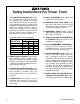
Safety Instructions For Power Tools 9. USE PROPER EXTENSION CORD. Make sure your extension cord is in good condition. Conductor size should be in accordance with the chart below. The amperage rating should be listed on the motor or tool nameplate. An undersized cord will cause a drop in line voltage resulting in loss of power and overheating. Your extension cord must also contain a ground wire and plug pin. Always repair or replace extension cords if they become damaged.
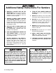
Additional Safety Instructions For Sanders 1. 2. 3. 4. MAINTAIN A SECURE GRIP ON THE WORKPIECE. The belt speed is approximately 1800 FPM. If control is lost, the workpiece can be propelled from the machine at extreme speed. CREATE A SAFETY ZONE AROUND THE SANDING SURFACE. If you can't control your workpiece with your hands at least 6" away from the sanding belt, you should create a jig or other device to hold the workpiece safely. REPLACE BELTS WHEN WORN OR DAMAGED.
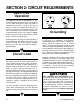
SECTION 2: CIRCUIT REQUIREMENTS 220V/110V Operation The Model G1140 has a dual-voltage 11⁄2 HP, 1720 RPM motor which has been pre-wired for use in a 220V single phase circuit. The cord set enclosed does not have a plug as the style of plug you require will depend upon the type of service you currently have or plan to install. If you will be installing a new receptacle and plug, we recommend either of the styles shown in Figure 1.
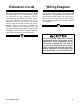
Extension Cords Wiring Diagram We do not recommend the use of extension cords on 220V equipment. It is much better to arrange the placement of your equipment and the installed wiring to eliminate the need for extension cords. Should it be necessary to use an extension make sure the cord is rated Hard Service (grade S) or better. Refer to the chart in Section 1: Safety Instructions to determine the minimum gauge for the extension cord. The extension cord must also contain a ground wire and plug pin.
SECTION 3: GENERAL INFORMATION Commentary We are proud to offer the Grizzly Model G1140 Edge Sander. The Model G1140 is part of a growing Grizzly family of fine woodworking machinery. When used according to the guidelines set forth in this manual, you can expect years of troublefree, enjoyable operation and proof of Grizzly’s commitment to customer satisfaction. The Model G1140 is intended for home and medium-duty professional use.
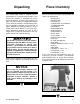
Unpacking Piece Inventory This G1140 Edge Sander is shipped from the manufacturer in a carefully packed carton. If you discover the machine is damaged after you’ve signed for delivery, and the truck and driver are gone, you will need to file a freight claim with the carrier. Save the containers and all packing materials for possible inspection by the carrier or its agent. Without the packing materials, filing a freight claim can be difficult.
Clean Up The unpainted surfaces are coated with a waxy oil to protect it from corrosion during shipment. Remove this protective coating with a solvent cleaner or citrus-based degreaser. Avoid chlorine-based solvents as they may damage painted surfaces should they come in contact. Always follow the usage instructions on the product you choose for clean up. Many of the solvents commonly used to clean machinery can be highly flammable, and toxic when inhaled or ingested.
SECTION 4: ASSEMBLY Beginning Assembly Assembly of the G1140 is straightforward. We have organized the assembly process into steps. Please follow them in sequence. Tools Required: Only a few common tools are needed to assemble this machine. Specifically, a 6" adjustable wrench, 12mm open end wrench, regular and Phillips® screwdriver and an 8mm Allen® wrench. Feet 1. Carefully lay the machine over on its side. Have someone assist you when doing this. Do not attempt to lay the machine over by yourself. 2.
Working Table 1. 3. Bolt the lead screw bracket to the front of the stand using the four Hex Bolts already threaded in place. See Figure 4. Locate the lead screw/table bracket assembly and the handwheel. Thread the handwheel onto the lead screw about halfway and insert the lead screw into the lead screw bracket. See Figure 6. Figure 6. Installing the lead screw assembly. Figure 4. Lead screw bracket Installed. 2. 4. Locate the vertical brace.
6. Measure the table bracket to the stand to assure it is parallel to the stand. See Figure 8. If the bracket is not parallel, remove the vertical brace, thread the horizontal brace in or out an appropriate amount and reinstall the vertical brace. 9. Leaving the table trunnion lock handles slightly loose, bolt the working table to the trunnions using the two (2) 5⁄16''-18 x 3⁄4'' hex bolts and 5⁄16'' flat washers supplied. See Figure 10.
Miter Body Set the miter body onto its pivot hole and secure into place with the plastic lock knob provided. See Figure 12. The miter body should only be used when sanding the ends of workpieces at least 8'' long. Do not use it as a back stop. Quick Release Lever 1. Loosen the belt tracking lock knob located at the top left of the machine. 2. Slide the quick release lever through the slot on the top of the platen cover. Thread it into place until it bottoms out. See Figure 13.
Auxiliary Table Dust Hood Slide the auxiliary table into place as pictured in Figure 14. Tighten the two thumb screws when table is at desired working height. It is not necessary to have the auxiliary table mounted at all times and can be installed only when needed. Bolt the dust hood on using the hex bolts already threaded in place. See Figure 15. Figure 15. Dust hood mounted in place. Figure 14. Installing the auxiliary table.
Belt Installation Back Stop Attach the back stop as shown in Figure 16. Set the back stop no more than 1⁄8'' from the sandpaper. This will prevent objects from being jammed between the back stop and the platen causing a potentially dangerous situation. 1. Loosen the belt tracking lock knob on the top left of the machine. Open the lid of the dust port and move the quick release lever to its locked open position. See Figure 17. Figure 17. Sander ready for belt installation. Figure 16.
SECTION 5: ADJUSTMENTS Belt Tracking 1. Carefully move the belt left to right by hand and adjust the tracking knob as necessary to achieve proper tracking. See Figure 19. 2. Before beginning this step, read the entitled Test Run on page 18. Connect to power and turn the machine on and off quickly. If the belt appears to track OK turn the machine on and fine tune the tracking. Tighten the tracking lock knob.
Table Tilt 1. Loosen the lock handles, tilt the working table to the desired angle and retighten the lock handles. See Figure 21. 2. It may be necessary to re-adjust the working table closer to the platen. Not more than a 1 ⁄4'' gap should exist between the platen and the working table. Table Height 1. Loosen lead screw lock handle and stabilizing shaft lock bolt. See Figure 22. 2. Turn hand wheel and position working table to desired height. 3. Retighten lock handle and lock bolt. Figure 22.
Platen Tilt 1. Loosen the lock bolt shown in Figure 23. 2. Carefully tilt the platen assembly over. Figure 24. 3. After returning the platen assembly back to its upright position, retighten the lock bolt depicted in Figure 23. Belt Tension Belt tension is preset at the factory and usually requires no adjustment. If the need to increase the tension should occur, unthread the retaining nut at the end of the idler roller mounting shaft. See Figure 25. Do not unthread the nut more than 1⁄2 its length.
SECTION 6: OPERATIONS Test Run Edge & End Sanding Once the assembly is complete and the adjustments are done to your satisfaction, you are ready to test the machine. Figure 26 depicts a typical edge sanding process. The back stop can be used for shorter workpieces if so desired. Turn on the power supply at the main panel. Press the START button. Make sure that your finger is poised on the STOP button, just in case there’s a problem.
Horizontal Sanding Contour Sanding When face sanding, tilt the platen so it is horizontal and use the back stop to hold your workpiece. Apply even hand pressure while moving the workpiece back and forth for even belt wear. When contour sanding, adjust the auxiliary table up or down so the workpiece is roughly centered on the roller. Move the workpiece over the roller to achieve your desired profile. Figure 28. Typical face sanding method. Figure 29. Typical contour sanding method.
SECTION 7: MAINTENANCE General Table Make a habit of inspecting your sander each time you use it. Check for the following conditions and repair or replace when necessary. The table and other non-painted surfaces on the Model G1140 should be protected against rust and pitting. Wiping the sander clean after every use ensures that moisture from sander dust isn’t allowed to trap moisture against bare metal surfaces. 1. Loose mounting bolts. 2. Worn switch. 3. Worn or damaged cords and plugs. 4.
SECTION 8: CLOSURE The following pages contain general machine data, parts diagrams/lists, troubleshooting guide and Warranty/Return information for your Model G1140 Edge Sander. If you need parts or help in assembling your machine, or if you need operational information, we encourage you to call our Service Department. Our trained service technicians will be glad to help you.
MACHINE DATA SHEET Customer Service #: (570) 326-3806 • To Order Call: (800) 523-4777 • Fax #: (800) 438-5901 GRIZZLY MODEL G1140 HEAVY DUTY EDGE SANDER Design Type .......................................................... Tilting Head Edge Sander, Floor Model Overall Dimensions and Specifications: Table Size ....................................................................................................22" x 101⁄2" Height (With Handle Up) ..............................................................
110 VOLT MOTOR WIRES BLACK YELLOW WHITE RED NOTE: THE WIRES FROM THE POWER SUPPLY, EXCEPT THE GREEN GROUND WIRE, ARE INTERCHANGABLE, THEREFORE COLORS ARE NOT SPECIFIED.
-24- G1140 Edge Sander 91 50 95 62 49A 45 63 60 103 63 52 78 103 6 57 7 8 58 51 75 63 44A 49 61 56 59 55 76 68 67 51 48 47 79 50 46A 80 91 92 99 78 71 97 78 100 74 73 52 5 81 69 74 104 4 3 2 40 43 65 66 32 72 41 81 5 64 42 76 105 28 33 23 39 1 4 26 25 35A 24 38 83 36 27 29 35A 30 97 98 22 16 101 19 20E 20C 24 102 20D 20B 21 76 23 13 11 10 9 18 17 15 14 20A 84 12
REF PART # 1 2 3 4 5 6 7 8 9 10 11 12 13 14 15 16 17 18 19 20A 20B 20C 20D 20E 21 22 23 24 25 26 27 28 29 30 32 33 35A 36 38 39 40 41 42 43 44A 45 P1531001 P1140002 PB24 PLW04 PSB14 P1531006 PN09 PLW06 PR02 P6204 P1531011 P1531012 P6205 PLW06 PN04 P1531016 PB03 P1140018 P1531019 P1531020A P1531020B PW02 PSB26 PSS03 P1531021 P1531022 P1531023 PSB03 P1531025 PB03 P1531027 P1531028 P1531029 P1531030 PN22 P1531033 PN08 P1531036 PB21 P1531039 P1531040 P1531041 P1531042 P1531043 P1023201 P1019Z016 DESCRIPTION
WARRANTY AND RETURNS Grizzly Industrial, Inc. warrants every product it sells for a period of 1 year to the original purchaser from the date of purchase. This warranty does not apply to defects due directly or indirectly to misuse, abuse, negligence, accidents, repairs or alterations or lack of maintenance.
WARRANTY CARD Name ____________________________________________________________________________________ Street ____________________________________________________________________________________ City ______________________________________________________________State________Zip_________ Phone Number_______________________E-Mail_______________________FAX________________________ MODEL # ______________________________Order #______________________________________________ The following information is given on a
FOLD ALONG DOTTED LINE Place Stamp Here GRIZZLY INDUSTRIAL, INC. P.O.