
- GRIZZLY 6" X 47" HEAVY-DUTY JOINTER INSTRUCTION MANUAL G1182HW, G1182ZHW, G1182Z, G1182ZX


G1182 6" Series Jointers -11-
SECTION 4: ASSEMBLY
Beginning Assembly
Most of your Model G1182 6'' Jointer has been
assembled at the factory, but some parts must be
assembled or installed after delivery. We have
organized the assembly process into steps.
Please follow along in the order presented here.
TOOLS REQUIRED: You will need a high quality
square, a long straightedge, 10mm, 12mm and
14mm open end wrenches, and a 3mm Allen
®
wrench.
Stand (G1182HW)
For reference, assemble the stand so the dust
chute end is on your left when facing the stand,
and the power switch is on your right.
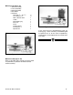
1. Begin by attaching the two ends to the front
panel with the machine screws and washers
provided. See Figure 3.
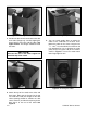
2. Mount the two dust chute sides to the dust
chute end as shown in Figure 4. Note that the
flanges are pointed away from the inside of
the chute. Do not fully tighten the screws yet.
Figure 3. Attachment of the two end panels.
All die-cut metal parts have a sharp edge
(called “flashing”) on them after they are
formed. This is removed at the factory.
Sometimes, though, a bit of flashing might
escape inspection. Please examine the
edges of all die-cut metal parts before han-
dling them or serious injury may occur.
Disconnect power to the
machine when perform-
ing any maintenance,
assembly or adjust-
ments. Failure to do this
may result in serious
personal injury.
Keep loose clothing
rolled up and out of the
way of machinery and
keep hair pulled back.
Wear safety glasses
during the entire assem-
bly process. Failure to
comply may result in
serious personal injury.