
- GRIZZLY 6" X 47" HEAVY-DUTY JOINTER INSTRUCTION MANUAL G1182HW, G1182ZHW, G1182Z, G1182ZX


G1182 6" Series Jointers -19-
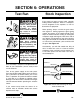
ADJUSTMENTS USING SPRINGS.
The knives are locked into the cutterhead with wedge-
type gibs and gib bolts. Jack screws under the knives
may be substituted with springs to help in the setting
process. When using springs, it is advised that the jack
screws be removed. To realign the knives:
1. Unplug the jointer!
2. Loosen the gib bolts until the knife is loose in the
slot. The gib bolts turn clockwise to loosen and
counterclockwise to tighten (when facing the head
of the bolt). Remove the knife and jack screws.
Place 1 spring in each of the two holes in bottom of
the knife slot. See Figure 16A and 16B.
3. Place the knife setting gauge on the cutterhead as
described previously, so the feet are securely
planted on the cutterhead. Make sure the gauge
extension rod is parallel to the cutterhead to main-
tain accuracy.
4. The downward pressure provided by the gauge
will set the knives at a uniform protrusion of approx-
imately .070" above the cutterhead. The knife
height should vary no more than .002"-.003"
across the length of the cutterhead.
5. Maintain a constant pressure on the gauge while
retightening the gib bolts.
6. Repeat the same procedure on the remaining
knives. As mentioned before, the standard knife
setting gauge is satisfactory for reasonably accu-
rate knife setting tasks.
Figure 16A shows the location of the springs.
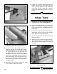
Outfeed Table
Facing the fence, the outfeed table is located to
the left of the cutterhead. The outfeed table must
be aligned to the highest point of the arc of the
blades. If it is set too high, the board will hit the
front edge of the table and be impossible to feed
over the jointer. If the table is set too low, the
back end of the board will fall into the cutterhead
and snipe will occur.
1. Loosen the table stop bolt jam nut under the
outfeed table. Turn the table stop bolt
counter-clockwise several times so that it will
not interfere when setting the correct table
height. See Figure 17.
2. Rotate the cutterhead by turning the motor
pulley. DO NOT grab the cutterhead itself.
Bring one blade to the approximate apex of its
arc.
3. Position a steel straightedge on the outfeed
table. Extend the straightedge over the middle
of the cutterhead. See Figure 18.
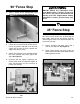
NOTICE
Model G1182HW uses handwheels for out-
feed and infeed table adjustments.
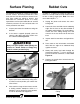
Knife
Spring
Gib Bolt
Gib
Figure 16B. Tightening the gib bolts.
Knife
Gib
Gib Bolt
Loosen
Tighten