COMBINATION SANDER MODEL G1183/G1276 INSTRUCTION MANUAL COPYRIGHT © 1989 BY GRIZZLY IMPORTS, INC. WARNING: NO PORTION OF THIS MANUAL MAY BE REPRODUCED IN ANY SHAPE OR FORM WITHOUT THE WRITTEN APPROVAL OF GRIZZLY IMPORTS, INC. REVISED APRIL, 1999. PRINTED IN U.S.A.
TABLE OF CONTENTS 1. 2. 3. 4. 5. 6. 7. 8. PAGE SAFETY RULES SAFETY RULES FOR POWER TOOLS . . . . . . . . . . . . . . . . . . . . . . . . . . . . . . . .2-3 ADDITIONAL SAFETY INSTRUCTIONS FOR THE SANDER . . . . . . . . . . . . . . . . .4 CIRCUIT REQUIREMENTS 110/220V OPERATION . . . . . . . . . . . . . . . . . . . . . . . . . . . . . . . . . . . . . . . . . . . . . .5 GROUNDING . . . . . . . . . . . . . . . . . . . . . . . . . . . . . . . . . . . . . . . . . . . . . . . . . . . . .5 FUSING . . . . .
SECTION 1: SAFETY For Your Own Safety Read Instruction Manual Before Operating This Equipment The purpose of safety symbols is to attract your attention to possible hazardous conditions. This manual uses a series of symbols and signal words which are intended to convey the level of importance of the safety messages. The progression of symbols is described below. Remember that safety messages by themselves do not eliminate danger and are not a substitute for proper accident prevention measures.
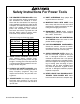
Safety Instructions For Power Tools 9. USE PROPER EXTENSION CORD. Make sure your extension cord is in good condition. Conductor size should be in accordance with the chart below. The amperage rating should be listed on the motor or tool nameplate. An undersized cord will cause a drop in line voltage resulting in loss of power and overheating. Your extension cord must also contain a ground wire and plug pin. Always repair or replace extension cords if they become damaged.
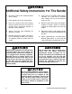
Additional Safety Instructions For The Sander 6. Even if you have a reliable method of dust collection, use a dust mask or respirator when sanding. Use eye and hearing protection as well. Never use excessive force when sanding. Doing so greatly increases the chance of personal injury, mechanical damage, or damage to your workpiece. 7. DO NOT sand material when you doubt its stability or integrity. Inspect all materials carefully for foreign objects like nails and staples. 4.
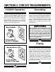
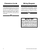
SECTION 2: CIRCUIT REQUIREMENTS 110/220V Operation Grounding The Model G1183/1276 is prewired for 110V, single phase operation. Figure 1 depicts the typical grounded receptacle which should be used. This machine can be rewired to operate at 220V, however a different plug will need to be installed. Figure 2 shows a typical 220V plug. A wiring diagram is provided at the back of the manual to show the two wiring configurations.
Extension Cords Wiring Diagram If you find it necessary to use an extension cord with the Model G1183/1276, make sure the cord is rated Hard Service (grade S) or better. Refer to the chart in the standard safety instructions to determine the minimum gauge for the extension cord. The extension cord must also contain a ground wire and plug pin. Always repair or replace extension cords when they become worn or damaged. Your G1183/1276 machine comes pre-wired for 110 volt operation.
SECTION 3: GENERAL INFORMATION Commentary Grizzly Industrial, Inc. is proud to offer the Model G1183 6" x 48" – 12" Disc Combination Sander and its slower-speed version, the Model G1276. This saw is a part of Grizzly’s growing family of fine woodworking machinery. When used according to the guidelines set forth in this manual, you can expect years of trouble-free, enjoyable operation, and proof of Grizzly’s commitment to customer satisfaction.
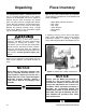
Unpacking Piece Inventory The Combination Sander is shipped from the factory in a carefully packed carton. If you find the machine to be damaged after you’ve signed for delivery and the truck and driver are already gone, you will need to file a freight claim with the carrier. Save the containers and all packing materials for inspection by the carrier or their agent. Without the packing materials, filing a freight claim can be difficult. If you need advice regarding this situation, please call us.
Clean Up The unpainted surfaces are coated with a waxy oil to protect it from corrosion during shipment. Remove this protective coating with a solvent cleaner or citrus-based degreaser. Avoid chlorine-based solvents as they may damage painted surfaces should they come in contact. Always follow the usage instructions on the product you choose for clean up. Many of the solvents commonly used to clean machinery can be highly flammable, and toxic when inhaled or ingested.
SECTION 4: ASSEMBLY Assembly Basics Most of your Combination Sander has been assembled at the factory. There are several simple steps to follow to complete the assembly. A few common tools will be required for assembly: Screwdrivers - medium and large straight blade or Phillips®, Allen® wrenches - 2mm, 3mm, 6mm and open end wrenches - 8mm and 10mm. Belt Table The belt table adjusts to allow you to sand your work at angles from -30° up to 45°.
Disc Table Belt Lever The disc table adjusts to allow you to sand your work at angles from -20° up to 45°. To install the disc table: The belt lever is used for releasing the tension on the idler pulley for belt installation. To attach the belt lever: 1. Loosen the two star knobs at either end of the disc table base until they reach the ends of their threaded rods. 1. Thread the belt lever onto the loosen/tighten collar and secure with the checknut. See Figure 7. 2.
SECTION 5: ADJUSTMENTS Proper adjustment of the Combination Sander is essential to ensure its optimum performance. The adjustments covered in this section are easily accomplished. Tables Tables should be square in both planes to execute precise work. Procedures for accomplishing this are described below. 1. Adjust the miter gauge to 90°. You can use it as a reference point from which to make other adjustments. 2.
6. Repeat this procedure with the 45° stop. You’ll need a known 45° angle, such as a speed square or the head of a combination square to check accuracy. Belt Platen The belt platen should be adjusted out far enough so it is flush with, or slightly higher than the upper roller. The rollers are slightly crowned, that is they are higher in the center than at the edges. This crowning helps the belt to stay centralized on the rollers.
Disc Guard Belt Arm Movement 1. Loosen the two screws (A and B) shown in Figure 12. These screws hold the guard in place. The 6" x 48" Belt Arm can be locked at any angle between horizontal and vertical for a variety of sanding applications. 2. Adjust the two vertically-aligned screws (C and D in Figure 12) so the guard is upright and not touching the disc. The top screw moves the guard toward the disc and the bottom screw moves it away from the disc. 1. Loosen the locking bolt as shown in Figure 13.
Belt Installation The 6'' x 48'' sanding belt is easily installed. First remove the belt guard by loosening the four combination-head screws. Pull down on the spring loaded belt tensioning lever which lowers the upper roller and allows the belt to be slid off of the two rollers. See Figure 14. Belt Tracking Tracking adjustment is conducted as follows: 1. Insure that the upper roller is parallel to the platen (there is no adjustment for the lower roller).
5. With the straightedge along the edge which is low, loosen the knurled locking nut and turn the tracking knob while watching the gap change between the straight edge and the roller. Make small changes and check for a change in gap on the opposite side. 6. When the gap has been equalized between the two sides, make sure the center of the roller, or the crown, is still approximately flush or just slightly above the platen surface. Lock the adjustment knobs with the locking knobs. 7. Reinstall the belt.
SECTION 6: OPERATIONS The aluminum disc accepts 12" diameter cloth or paper-backed PSA sanding discs. The belt sander requires a 6" x 48" sanding belt. For disc or belt sanding, we recommend a 100-grit (medium) material for general sanding chores, a 60-grit (coarse) material for rough work, and a 150-grit (fine) surface for finish work. See the current Grizzly catalog for prices and ordering information. Please review all safety rules for sanders and all power tools before attempting operation.
Disc Sanding 1. Loosen table lock knob and tilt work table to desired angle. Tighten lock knob. 2. Use miter gauge to guide work into position. 3. Ease workpiece into the half of the disc that spins down toward the table. See Figure 17. Surface Sanding To remove a large amount of material quickly from a large surface area, use the belt arm in its horizontal position. 1. Turn the sander on and let it reach its full working speed. 2. Place the workpiece flat on the belt.
Bevel Sanding Miter Sanding When bevel sanding, be sure to re-position the work table so it is at a maximum of 1/16" away from the disc or belt. The most efficient way to get a perfect miter is to cut the workpiece slightly long and sand it to the desired dimension. Miter sanding can be done on either the belt or the disc. 1. Hold workpiece against miter gauge to keep piece square to the disc or belt. 2. Move workpiece against sanding surface width to ensure even abrasion. Use even, but firm, pressure.
SECTION 7: MAINTENANCE General Tables The Combination Sander is ruggedly constructed to provide years of dependable service. To ensure that you enjoy maximum performance and longevity, we suggest the following routine maintenance: The tables and other non-painted surfaces on the Model G1183 and G1276 should be protected against rust and pitting. Wiping the sander clean after every use ensures that moisture from wood dust isn’t allowed to trap moisture against bare metal surfaces. 1.
NOTES G1183/1276 Combination Sander -21-
SECTION 8: CLOSURE The following pages contain general machine data, part diagrams/lists, troubleshooting guide and Warranty/Return information for your Model G1183/1276 Combination Sander. If you need parts or help in assembling your machine, or if you need operational information, we encourage you to call our Service Department. Our trained service technicians will be glad to help you.
G1183/1276 Combination Sander -23-
MACHINE DATA SHEET Customer Service #: (570) 326-3806 • To Order Call: (800) 523-4777 • Fax #: (800) 438-5901 GRIZZLY MODEL G1183 COMBINATION SANDER Design Type.................................................................................................... Bench Model Overall Dimensions: Height (Belt arm horizontal) ..................................................................................141⁄2" Height (Belt arm vertical) .........................................................................
MACHINE DATA SHEET Customer Service #: (570) 326-3806 • To Order Call: (800) 523-4777 • Fax #: (800) 438-5901 GRIZZLY MODEL G1276 COMBINATION SANDER Design Type ....................................................................................................Bench Model Overall Dimensions: Height (Belt arm horizontal) ..................................................................................141⁄2" Height (Belt arm vertical) .........................................................................
MAIN UNIT PARTS DIAGRAM -26- G1183/1276 Combination Sander
PARTS LIST REF# PART# DESCRIPTION REF# PART# 001 P1183001 STAND 034 PSS12M SET SCREW M6-1.0 x 25mm 002 P1183002 BASE PLATE 035 P1183035 DISC GUARD 003 PB17M HEX BOLT M8-1.
NOTES -28- G1183/1276 Combination Sander
MOTOR UNIT PARTS DIAGRAM REF# PART# DESCRIPTION 068 P1183068 COVER 070 P1183070 PLATE 071 PSB14M CAP SCREW M8-1.
WARRANTY AND RETURNS Grizzly Industrial, Inc. warrants every product it sells for a period of 1 year to the original purchaser from the date of purchase. This warranty does not apply to defects due directly or indirectly to misuse, abuse, negligence, accidents, repairs or alterations or lack of maintenance.
WARRANTY CARD Name ____________________________________________________________________________________ Street ____________________________________________________________________________________ City ______________________________________________________________State________Zip_________ Phone Number_______________________E-Mail_______________________FAX________________________ MODEL # ______________________________Order #______________________________________________ The following information is given on a
FOLD ALONG DOTTED LINE GRIZZLY INDUSTRIAL, INC. P.O.