EDGE SANDER MODEL G1531 INSTRUCTION MANUAL COPYRIGHT © 1989 BY GRIZZLY INDUSTRIAL, INC. REG. # TX 3 170 581 WARNING: NO PORTION OF THIS MANUAL MAY BE REPRODUCED IN ANY SHAPE OR FORM WITHOUT THE WRITTEN APPROVAL OF GRIZZLY INDUSTRIAL, INC. REVISED FEBRUARY, 1999.
Table Of Contents 1. 2. 3. 4. 5. 6. PAGE INTRODUCTION ........................................................................................................3 SAFETY RULES FOR ALL TOOLS ....................................................................4-5 UNPACKING............................................................................................................6 PIECE INVENTORY ................................................................................................6 CLEAN UP .....
SECTION 1: INTRODUCTION Grizzly Industrial, Inc. is proud to offer the Model G1531 Edge Sander. This sander is a part of Grizzly’s growing family of fine woodworking machinery. When used according to the guidelines stated in this manual, you can expect years of trouble-free, enjoyable operation. The Model G1531 is intended for home and medium-duty professional use. This sander features a 1,720 RPM, 11/2 H.P. capacitor-start motor, mechanical ON/OFF switch, 4'' dust port and a cast iron working table.
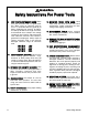
SAFETY RULES FOR ALL TOOLS For Your Own Safety Read Instruction Manual Before Operating This Equipment The purpose of safety symbols is to attract your attention to possible dangers. This manual uses a series of symbols which are intended to convey the level of criticality of the safety message. The progression of symbols is described below. Remember that safety messages by themselves do not eliminate danger and are not a substitute for proper accident prevention measures.
Safety Instructions For Power Tools 9. 10. USE PROPER EXTENSION CORD. Make sure your extension cord is in good condition. When using an extension cord, be sure it is rated Hard Service (grade S) or better. Conductor size must be 16 A.W.G. for cords up to 100 feet in length. An undersized cord will cause a drop in line voltage resulting in loss of power and overheating. Your extension cord must also contain a ground wire and plug pin. Always repair or replace extension cords if they become damaged.
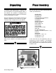
Unpacking Piece Inventory The Model G1531 Edge Sander is shipped from the manufacturer in a carefully packed carton. If you discover the machine is damaged after you’ve signed for delivery, please call Customer Service immediately for advice. After all the parts have been removed from the carton, you should have: Save the containers and all packing materials for possible inspection by the carrier or its agent. Otherwise filing a freight claim can be difficult.
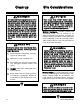
Clean up Site Considerations The table and other unpainted parts of the Model G1531 are coated with a waxy oil that protects them from corrosion during shipment. Remove the protective coating with mineral spirits and paper towels. Do not use gasoline or other petroleum based solvents because of their extremely low flash points. Do not use chlorinebased solvents – if you happen to splash some onto a painted surface, you’ll ruin the finish. Serious personal injury may occur.
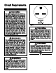
Circuit Requirements The motor supplied with the G1531 is a dual-voltage 110/220V motor prewired for 220V. Under normal use, the motor draws approximately 10 amps @ 220V. We recommend using a 15 amp circuit breaker or a 20 amp fuse for 220V operation. This should be satisfactory for normal use, while preventing motor damage from high heat caused by overload. The circuit you use should be dedicated, (i.e., the G1531 should provide the only draw from that circuit).
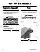
SECTION 2: ASSEMBLY Feet Beginning Assembly Assembly of the G1531 is straightforward. We have organized the assembly process into steps. Please follow them in sequence. All die-cut metal parts have a sharp edge (called “flashing”) on them after they are formed. This is removed at the factory. Sometimes a bit of flashing might escape inspection. Please examine the edges of all die-cut metal parts before handling them. Serious personal injury may occur. 1. Carefully lay the machine over on its side.
Working Table 1. 3. Locate the lead screw / table bracket assembly and the handwheel. Thread the handwheel onto the lead screw about halfway and insert the lead screw into the lead screw bracket. Figure 6. Bolt the lead screw bracket to the front of the stand using the four Hex Bolts already threaded in place. Figure 4. Figure 6. Installing the lead screw assembly. Figure 4. Lead screw bracket Installed. 2.
7. Measure the table bracket to the stand to assure it is parallel to the stand. Figure 8. If the bracket is not parallel, remove the vertical brace, thread the horizontal brace in or out an appropriate amount and reinstall the vertical brace. 10. Leaving the table trunnion lock handles slightly loose, bolt the working table to the trunnions using the two 5⁄16''-18 x 3⁄4'' Hex Bolts and 5⁄16'' Flat Washers supplied. Figure 10.
Miter Body Set the miter body onto its pivot hole and secure into place with the plastic lock knob provided. Figure 12. The miter body should only be used when sanding the ends of workpieces at least 8'' long. Do not use it as a back stop. Quick Release Lever 1. Loosen the belt tracking lock knob located at the top left of the machine. 2. Slide the quick release lever through the slot on the top of the platen cover. Thread it into place until it bottoms out. Figure 13.
Auxiliary Table Dust Hood Slide the auxiliary table into place as pictured in Figure 14. It is not necessary to have the auxiliary table mounted at all times and can be installed only when needed. Bolt the dust hood on using the hex bolts already threaded in place. Figure 15. Figure 15. Dust hood mounted in place. Figure 14. Installing the auxiliary table.
Belt Installation 1. Loosen the belt tracking lock knob on the top left of the machine. Open the lid of the dust port and move the quick release lever to its locked open position. Figure 16. 2. Check the back side of the belt for an arrow indicating direction of rotation. The sanding belt rotates counter-clockwise. 3. Slide the belt over the rollers. Move the quick release lever back to its tensioned position. Figure 17. Belt tracking is covered in the next section. Figure 17. Belt installed.
SECTION 3: ADJUSTMENTS Belt Tracking 1. Carefully move the belt left to right by hand and adjust the tracking knob as necessary to achieve proper tracking. Figure 18. 2. Before beginning this step, read the Safety Rules on page 17 and Test Run on page 18. Connect to power and turn the machine on and off quickly. If the belt appears to track OK turn the machine on and fine tune the tracking. Tighten the tracking lock knob.
Table Tilt 1. Loosen the lock handles, tilt the working table to the desired angle and retighten the lock handles. Figure 20. 2. It may be necessary to re-adjust the working table closer to the platen. Not more than a 1 ⁄4'' gap should exist between the platen and the working table. Figure 21.Table height adjustments. Belt Tension Figure 20. Lock handle underneath the table. Belt tension is preset at the factory and usually requires no adjustment.
SECTION 4: OPERATIONS Edge Sander Safety Rules The Model G1531 is capable of causing severe injury if used in a reckless manner. Please follow the previously-mentioned safe ty rules for all tools, as well as these safety guidelines for edge sanders: 8. Compound sanding should always be fully supported. 9. Always support round stock in a V-block. 10. Stand in front of the machine at all times. 1.
Always wear ANSI-approved safety glasses or goggles and hearing protection when operating equipment — particularly when testing new tools or machinery. Do not allow visitors into your workshop when testing or operating equipment unless they are also properly protected. Serious personal injury may occur. Test Run Once the assembly is complete and the adjustments are done to your satisfaction, you are ready to test the machine. DO NOT attempt to investigate or adjust the machine while it is running.
Edge & End Sanding Contour Sanding Figure 23 depicts a typical edge sanding process. When contour sanding, adjust the auxiliary table up or down so the workpiece is roughly centered on the roller. Move the workpiece over the roller to achieve your desired profile. Figure 25. Figure 23. Edge sanding process. Figure 24 depicts a typical method for sanding the end of a workpiece. Figure 25. Contour sanding on auxiliary table. Figure 24. Sanding the end of a piece.
SECTION 5: MAINTENANCE General Before performing any type of inspection or maintenance work, be sure that the power cord is unplugged and all moving parts have come to a complete stop. Serious personal injury may occur. Make a habit of inspecting your sander each time you use it. Check for the following conditions and repair or replace when necessary. 1. Loose mounting bolts. 2. Worn switch. 3. Worn or damaged cords and plugs. 4. Damaged sanding belt. 5.
SECTION 6: CLOSURE The following pages contain general machine data, parts diagram, parts list and Warranty/Return information for your Model G1531 Edge Sander. If you need parts or help in assembling your machine, or if you need operational information, we encourage you to call the Service Department listed in the Introduction. Our trained service technicians will be glad to help you.
MACHINE DATA SHEET Customer Service #: (570) 326-3806 • To Order Call: (800) 523-4777 • Fax #: (800) 438-5901 GRIZZLY MODEL G1531 HEAVY DUTY EDGE SANDER Design Type.................................................................................................... Bench Model Overall Dimensions and Specifications: Table Size ................................................................................................221⁄8" x 101⁄2" Height (With Handle Up) ................................................
REF# PART # 1 2 3 4 5 6 7 8 9 10 11 12 13 14 15 16 17 18 19 20A 20B 20C 20D 20E 21 22 23 24 25 26 27 28 29 30 31 32 33 34 35A 36 39 -2240 41 42 43 44 P1531001 P1531002 PB24 PLW04 PSB14 P1531006 PN09 PLW06 PR02 P6204 P1531011 P1531012 P6205 PLW06 PN04 P1531016 PB03 P1140018 P1531019 P1531020A P1531020B PW02 PSB26 PSS10 P1531021 P1531022 P1531023 PSB03 P1531025 PB03 P1531027 P1531028 P1531029 P1531030 PN13 PN18 P1531033 PB03 PN08 P1531036 P1531039 P1531040 P1531041 P1531042 P1531043 P1023201 -22- DESCRIP
45 48 50 86 62 49A G1531 Edge Sander -23- 63 60 85 63 52 78 85 6 52 7 8 58 63 75A 53 44 49 61 56 59 55 76 51 68 67 79 47 47A 48 50 46A 49B 70 87 80 78 71 74 73 52 5 81 4 3 2 40 43 69 74 65 66 32 31 72 41 81 5 64 42 76 28 33 23 39 25 24 34 1 83 36 35A 4 26 27 20D 20C 29 35 30 21 20B 16 22 20E 24 19 76 23 13 11 9 10 18 17 15 14 20A 84 12
WARRANTY AND RETURNS Grizzly Industrial, Inc. warrants every product it sells for a period of 1 year to the original purchaser from the date of purchase. This warranty does not apply to defects due directly or indirectly to misuse, abuse, negligence, accidents, repairs or alterations or lack of maintenance.
WARRANTY CARD Name ____________________________________________________________________________________ Street ____________________________________________________________________________________ City ______________________________________________________________State________Zip_________ Phone Number_______________________E-Mail_______________________FAX________________________ MODEL # ______________________________Order #______________________________________________ The following information is given on a
FOLD ALONG DOTTED LINE Place Stamp Here GRIZZLY INDUSTRIAL, INC. P.O.