COMBINATION SANDER MODEL G5049Z INSTRUCTION MANUAL COPYRIGHT © 1997 BY GRIZZLY INDUSTRIAL WARNING: NO PORTION OF THIS MANUAL MAY BE REPRODUCED IN ANY SHAPE OR FORM WITHOUT THE WRITTEN APPROVAL OF GRIZZLY INDUSTRIAL, INC. OCTOBER, 1997. PRINTED IN TAIWAN DISCONTINUED MACHINE MANUAL DISCLAIMER THE INFORMATION IN THIS MANUAL REPRESENTS THE LAST CONFIGURATION OF THE MACHINE BEFORE IT WAS DISCONTINUED. MACHINE CONFIGURATIONS MAY HAVE CHANGED AS PRODUCT IMPROVEMENTS WERE INCORPORATED.
WARNING Some dust created by power sanding, sawing, grinding, drilling, and other construction activities contains chemicals known to the State of California to cause cancer, birth defects or other reproductive harm. Some examples of these chemicals are: • Lead from lead-based paints. • Crystalline silica from bricks, cement, and other masonry products. • Arsenic and chromium from chemically treated lumber. Your risk from these exposures varies, depending on how often you do this type of work.
Table Of Contents PAGE 1. SAFETY ....................................................................................................................2 SAFETY RULES FOR ALL TOOLS ....................................................................2 ADDITIONAL SAFETY INSTRUCTIONS FOR SANDERS..................................3 2. CIRCUIT REQUIREMENTS...................................................................................... 4 110V OPERATION ........................................................
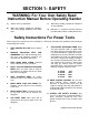
SECTION 1: SAFETY WARNING: For Your Own Safety Read Instruction Manual Before Operating Sander a) Always wear eye protection. c) When disc sanding, support the workpiece on the worktable. b) When belt sanding, support the workpiece with a miter gauge, backstop or the worktable. d) Maintain 1⁄16'' maximum clearance between the work table and the sanding belt or disc. Safety Instructions For Power Tools These safety rules cannot cover every situation in a work shop.
12. SECURE WORK. Use clamps or a vise to hold work when practical. It’s safer than using your hand and frees both hands to operate tool. 17. USE RECOMMENDED ACCESSORIES. Consult the owner’s manual for recommended accessories. The use of improper accessories may cause risk of injury to persons. 13. DON’T OVERREACH. Keep proper footing and balance at all times. 18. CHECK DAMAGED PARTS.
SECTION 2: CIRCUIT REQUIREMENTS 110V Operation The 11⁄2 H.P. motor will safely draw 16 amps at 110V. If you operate this sander on any circuit that is already close to its capacity, it might blow a fuse or trip a circuit breaker. However, if an unusual load does not exist, and power failure still occurs, have the circuit inspected by a qualified electrician. Under no circumstances should the grounding pin from any three-pronged plug be removed.
SECTION 3: GENERAL INFORMATION We are proud to bring you the Model G5049Z Combination Sander. The Model G5049Z is part of a growing Grizzly family of fine woodworking machinery. When used according to the guidelines set forth in this manual, you can expect years of trouble-free, enjoyable operation and proof of Grizzly’s commitment to customer satisfaction. The Model G5049Z is a combination 6" x 48" belt and 12" disc sander that is capable of a wide variety of operations.
Unpacking Piece Inventory The Model G5049Z Sander is shipped from the manufacturer in a carefully packed carton. If you discover the machine is damaged after you’ve signed for delivery, please call our Customer Service number immediately for advice. After all the parts have been removed from the container, you should have: 1 1 1 1 1 1 1 4 4 4 1 1 1 1 Save the containers and all packing materials for possible inspection by the carrier or its agent. Otherwise filing a freight claim can be difficult.
Clean up The work table and other unpainted parts of the Model G5049Z are coated with a waxy oil that protects them from corrosion during shipment. Remove the protective coating with mineral spirits and cloth rags. Do not use gasoline or other petroleum based solvents because of their extremely low flash points. Do not use chlorinebased solvents – if you happen to splash some onto a painted surface, you’ll ruin the finish. Site Considerations 1.
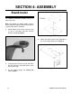
SECTION 4: ASSEMBLY Stand/motor The G5049Z Combination Sander stand is an open frame style. Note: Assembling the G5049 Sander requires heavy lifting. We strongly recommend having an assistant help with the assembly. 1. Attach Rubber Feet to base using the four 5 ⁄16''-18 x 1'' Hex bolts, Hex Nuts and Flat Washers provided. Figure 2. Figure 3. 4. Attach the motor mount to the underside of the stand. Finger tighten only. Figure 4. Figure 2. 2.
5. Mount the motor to the motor mount. Leave the bolts finger tight for now. 6. Lift the spring loaded side of the jackshaft assembly up and insert a 1⁄16'' shim between the cast bearing block and the aluminum pad. 7. Lift the motor up and slip the two flat bars between the stand top and the motor drive disc. Let the weight of the motor rest on the flat bars. Tighten down the motor mount bolts. Wiring The Motor 1. Remove the wire box cover. 2.
SECTION 5: ADJUSTMENTS Belt Replacement Belt Tracking With the exception of Belt Tracking, adjustments to your Combination Sander should be made with the power off and the machine unplugged. The goal of this procedure is to achieve proper belt tracking that prevents the belt from wandering off to either side. Unlock the Quick-Release Lever by pulling the lever straight out. Figure 7. Slide the belt off the rollers straight toward you. Reverse this process to install a new belt. 1.
Belt Tensioning 2. Correct belt tension will insure that your sander functions properly. Too little tension will allow the belt to slip and may cause the sander to track erratically. Too much will cause the drive drum to creep on the drive shaft and possibly cause premature bearing failure. It is impossible to describe ideal belt tension. A good rule of thumb is less tension is better than too much. If the belt sounds like a drum when plucked, your tension is probably set too tight.
SECTION 6: OPERATIONS Horizontal Sanding Test Run Once assembly is complete and adjustments are done to your satisfaction, you are ready to test the machine. Turn on the power supply at the main panel. Press the START button. Make sure that your finger is poised on the STOP button, just in case there’s a problem. The sander should run smoothly, with little or no vibration or rubbing noises. Strange or unnatural noises should be investigated and corrected before operating the machine further.
Curved Sanding To sand curves, use the end of the belt arm. Hold the workpiece firmly and apply light, even pressure to the belt. To avoid excessive loading of the belt in one area, move workpiece slowly across entire surface of belt. Figure 12. Disc Sanding 1. Loosen table lock knob and tilt work table to desired angle. Tighten lock knob. 2. Ease workpiece into the half of the disc that spins down toward the table. Figure 13. 3.
SECTION 7: MAINTENANCE General Lubrication Make a habit of inspecting your sander each time you use it. Check for the following conditions and repair or replace when necessary. Your combination sander is equipped with shielded and pre-lubricated ball bearings and require no lubrication for the life of the bearings. All bearings are common sizes and are readily available from a local bearing supply house or our Service Department. 1. Loose mounting bolts. 2. Worn switch. 3.
SECTION 8: CLOSURE The following pages contain general machine specifications, parts diagram and list and Warranty/Return information for your Model G5049Z Combination Sander. If you need parts or help in assembling your machine, or if you need operational information, we encourage you to call our Service Department. Our trained service technicians will be glad to help you.
-16- G5049Z Combination Sander
G5049Z Combination Sander -17-
-18- G5049Z Combination Sander
G5049Z Combination Sander -19-
-20- G5049Z Combination Sander
REF PART # DESCRIPTION REF PART # 01 02 03 04 05 06 07 08 09 10 11 12 13 14 15 16 17 18 19 20 21 22 23 24 25 26 27 28 29 30 31 32 33 34 35 P5049001 P5049002 P5049003 P5049004 P5049005 P5049006 P5049007 P5049008 P5049009 P5049010 P5049011 P5049012 P5049013 P5049014 P5049015 P5049016 P5049017 P5049018 P5049019 P5049020 P5049021 P5049022 P5049023 P5049024 P5049025 P5049026 SEE CAT P5049028 P5049029 P5049030 P5049031 P5049032 P5049033 P5049034 P5049035 MAIN BODY TRUNNION,LEFT TRUNNION,RIGHT DISC TABLE BR
REF PART # DESCRIPTION REF PART # DESCRIPTION 71 72 73 74 75 76 77 78 79 80 81 82 83 84 85 86 87 88 89 90 91 92 93 94 95 96 97 98 99 100 101 102 103 104 105 106 107 P5049071 P5049072 P5049073 P5049074 P5049075 P5049076 P5049077 P5049078 P5049079 P5049080 P5049081 P5049082 P5049083 P5049084 P5049085 P5049086 P5049087 P5049088 P5049089 P5049090 P5049091 P5049092 P5049093 P5049094 P5049095 P5049096 P5049097 P5049098 P5049099 P5049100 P5049101 P5049102 P5049103 P5049104 P5049105 P5049106 P5049107 WASHER
Machine Data GRIZZLY MODEL G5049Z COMBINATION SANDER Design Type .......................................................................................................................... Floor Model Overall Dimensions and Specifications: Base ........................................................................................................................20 x 27 3⁄4"" Height (Belt arm horizontal) ............................................................................................
WARRANTY AND RETURNS Grizzly Industrial, Inc. warrants every product it sells for a period of 1 year to the original purchaser from the date of purchase. This warranty does not apply to defects due directly or indirectly to misuse, abuse, negligence, accidents, repairs or alterations or lack of maintenance.