6" x 12" SURFACE GRINDER MODEL G5963 INSTRUCTION MANUAL COPYRIGHT ©2000 BY GRIZZLY INDUSTRIAL, INC. WARNING: NO PORTION OF THIS MANUAL MAY BE REPRODUCED IN ANY SHAPE OR FORM WITHOUT THE WRITTEN APPROVAL OF GRIZZLY INDUSTRIAL, INC.
Table Of Contents PAGE 1. 2. 3. 4. 5. 6. 7. SAFETY SAFETY INSTRUCTIONS FOR POWER TOOLS ................................................2-3 ADDITIONAL SAFETY INSTRUCTIONS FOR SURFACE GRINDERS ..................4 CIRCUIT REQUIREMENTS 110V OPERATION ....................................................................................................5 220V OPERATION ....................................................................................................5 GROUNDING ............................
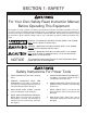
SECTION 1: SAFETY For Your Own Safety Read Instruction Manual Before Operating This Equipment The purpose of safety symbols is to attract your attention to possible hazardous conditions. This manual uses a series of symbols and signal words which are intended to convey the level of importance of the safety messages. The progression of symbols is described below. Remember that safety messages by themselves do not eliminate danger and are not a substitute for proper accident prevention measures.
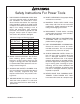
Safety Instructions For Power Tools 9. USE PROPER EXTENSION CORD. Make sure your extension cord is in good condition. Conductor size should be in accordance with the chart below. The amperage rating should be listed on the motor or tool nameplate. An undersized cord will cause a drop in line voltage resulting in loss of power and overheating. Your extension cord must also contain a ground wire and plug pin. Always repair or replace extension cords if they become damaged.
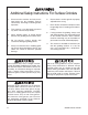
Additional Safety Instructions For Surface Grinders 1. Ensure that the machine sits firmly on the floor before use. Any “wobbles” must be corrected by shimming or blocking before operation. 2. This machine is not designed to process any other material except metals. 3. Never position fingers or hands directly between the grinding wheel and the table. 4. Do not operate surface grinder with cracked or damaged grinding wheels. 5. Always use extreme care in handling grinding wheels during installation.
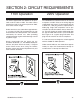
SECTION 2: CIRCUIT REQUIREMENTS 110V Operation 220V Operation The motor supplied with the G5963 can be operated at either 110V or 220V. The motor comes prewired for 110V. If you wish to operate at 220V, refer to the section at right. The G5963 Surface Grinder motor can be rewired to operate at 220V. Refer to the wiring diagram supplied with this manual. If converting to operate at 220V, the 110V plug must be replaced with a 220V plug.
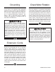
Grounding Check Motor Rotation In the event of an electrical short, grounding reduces the risk of electric shock by providing a path of least resistance to disperse electric current. This tool is equipped with a power cord having an equipment-grounding conductor. See Figure 1 and 2. The outlet must be properly installed and grounded in accordance with all local codes and ordinances. After the machine is assembled and properly connected to electrical power, test the motor rotation.
SECTION 3: GENERAL INFORMATION Commentary We are proud to offer the Grizzly Model G5963 Surface Grinder. The Model G5963 is part of a growing Grizzly family of fine metalworking machinery. When used according to the guidelines set forth in this manual, you can expect years of trouble-free, enjoyable operation and proof of Grizzly’s commitment to customer satisfaction. The Model G5963 is intended for home and professional use.
Unpacking Parts Inventory The surface grinder is shipped from the factory in two carefully packed crates. If you find the machine to be damaged after you’ve signed for delivery and the truck and driver are already gone, you will need to file a freight claim with the carrier. Save the containers and all packing materials for inspection by the carrier or their agent. Without the packing materials, filing a freight claim can be difficult.
Clean Up The unpainted surfaces are coated with a waxy oil to protect them from corrosion during shipment. Remove this protective coating with a solvent cleaner or degreaser such as Grizzly’s G7895 Citrus-based Degreaser. Avoid chlorinebased solvents as they may damage painted surfaces should they come in contact. Always follow the usage instructions on the product you choose for clean up. Follow the safety rules listed below when working with solvents. 1.
SECTION 4: ASSEMBLY Lifting the Grinder Mounting on Stand The majority of the weight of the Surface Grinder is the grinding head. Take great care when lifting this unit from the crate and moving it into position on the stand. Remove the table from the crate first and set it aside until the grinder is completely secured to the stand. Locate the stand as close to its final position as possible.
Table and Handwheel Guard Wipe the V-grooves of the table and the saddle down with way oil (Mobil Vactra #2 or equivalent). The table rests by its own weight on the ways, and is oiled by the lubrication system. Set the sliding table in position on the saddle. Make sure the gear on the underside of the table engages with the gear on the handwheel shaft. Attach the Guard to the left hand side of the table using the socket head cap screws provided.
SECTION 5: OPERATIONS Overview Once assembly has been completed, the G5963 Surface Grinder is ready for use in the shop. Many adjustments have already been made at the factory, yet we recommend you familiarize yourself with all of the following procedures to gain a better understanding of the Surface Grinder’s construction and operation. DO NOT make adjustments while the surface grinder is running. Ensure that the switch is off, power is disconnected and moving parts have stopped before making adjustments.
Wheel Selection Wheel Mounting Aluminum oxide and silicon carbide wheels are marked in a somewhat uniform manner by all the major manufacturers. Understanding these markings will help you understand the capabilities of various wheels. Always refer to the manufacturer’s grinding recommendations when selecting a wheel for your project. Before mounting any wheel, check it for integrity by performing a “ring check”.
4. Remove the Wheel Sleeve from the back side of the wheel. 5. Take the new grinding wheel and insert the Wheel Sleeve into the bore from the back of the wheel. Most wheels will have a paper disc on each side, this helps to equalize the clamping pressure. Do not remove these discs! The Wheel Sleeve should fit snugly in the bore of the wheel. If it is too loose, do not attempt to fill the gap with any other types of material. The wheel will not maintain proper balance.
Wheel Dressing 2. Lower the Vertical Adjustment Handwheel so the grinding wheel just comes in contact with the Dressing Diamond. Dressing is performed on the face of the grinding wheel to sharpen the abrasives or to remove material which has imbedded in the surface. Dressing also makes the circumference of the wheel true to its centerpoint, thus insuring good grinding results. Wheels should always be dressed when first installed on the machine, and also periodically as the wheel is used.
Oil Pump Typical Operation The critical components of the machine are lubricated by means of the oil pump located on the left hand side of the machine. See Figure 8. Check the oil level periodically. Add new oil (Use a Way Oil such as Mobil Vactra #2 or equivalent) as needed to maintain the fluid level in the Oil Pump. Operation of the grinder is controlled through the location and movement of the three handwheels. The Vertical Adjustment Handwheel controls the up and down movement of the grinding head.
Accessories Test Run In order to properly use this machine it is necessary to purchase some type of holding fixture. The workpiece must be firmly secured before beginning any type of grinding operations. Refer to the current Grizzly catalog for options. The most versatile holding device is a magnetic chuck. See Figure 10. With the throw of a lever anything magnetic can be firmly attached to the table without having jaws or fingers which might interfere with the grinding wheel.
SECTION 6: MAINTENANCE General Grinding Wheels Make a habit of inspecting your Surface Grinder each time you use it. Check for the following conditions and repair or replace when necessary: The grinding wheel should be inspected before every use. Use the ring check method noted in the Grinding Wheel section in Operations to verify the structural integrity. If using coolant during grinding, always run the wheel for 5-10 minutes at the end of the operation to remove any coolant from the wheel.
SECTION 7: CLOSURE The following pages contain parts diagrams, parts lists, general machine data and warranty/return information for your Model G5963 Surface Grinder. If you need parts or help in assembling your machine, or if you need operational information, we encourage you to call the Grizzly Industrial Service Department. Our trained service technicians will be glad to help you.
MACHINE DATA SHEET Customer Service #: (570) 326-3806 • To Order Call: (800) 523-4777 • Fax #: (800) 438-5901 GRIZZLY MODEL G5963 MANUAL SURFACE GRINDER Design Type ......................................................................................................Floor Model Overall Dimensions: Height ....................................................................................................................571⁄2'' Length ..........................................................................
TROUBLESHOOTING This section covers the most common processing problems encountered in grinding and what to do about them. Do not make any adjustments until surface grinder is unplugged and moving parts have come to a complete stop. SYMPTOM POSSIBLE CAUSE Motor will not start. 1. 2. Low voltage. 1. Open circuit in motor or loose 2. connections. Check power line for proper voltage. Inspect all lead connections on motor for loose or open connections. Motor will not start; fuses or 1.
G5963 Surface Grinder Wiring Diagram 110 Volt Operation Z1 V1 U1 V2 U2 Z2 To Switch 220 Volt Operation Z1 V1 U1 V2 U2 Z2 To Switch -22- G5963 Surface Grinder
Ref# Part# Description Ref# Part# Description 001 P5963001 BASE 051 P5963051 ADJUSTMENT SCREW 002 P5963002 BASE W/ DOVETAIL GROOVE 052 P5963052 ELEVATION NUT 003 P5963003 OIL PIPE ELBOW 053 P5963053 ELEVATION LEAD SCREW 004 P5963004 BEARING BLOCK 054 PK48M KEY 4 X 4 X 20 005 PSB24M CAP SCREW M5-.8 X 16 055 P5963055 BALL BEARING 006 P5963006 BEARING 60202 056 P5963056 SEAT 007 P5963007 LOCKWASHER 057 P5963057 THRUST BEARING 008 PS09M PHLP HD SCR M5-.
G5963 SURFACE GRINDER - LOWER ASSEMBLY -24- G5963 Surface Grinder
G5963 SURFACE GRINDER - UPPER ASSEM- G5963 Surface Grinder -25-
WARRANTY AND RETURNS Grizzly Industrial, Inc. warrants every product it sells for a period of 1 year to the original purchaser from the date of purchase. This warranty does not apply to defects due directly or indirectly to misuse, abuse, negligence, accidents, repairs or alterations or lack of maintenance.
WARRANTY CARD NAME_______________________________________________ PHONE NUMBER___________________ STREET________________________________________________________________________________ CITY_______________________________STATE_________ZIP ___________________________________ INVOICE#_________________ MODEL# _G5963 Surface Grinder_______________ The following information is given on a voluntary basis. This information will be used for marketing purposes to help Grizzly develop better products.
FOLD ALONG DOTTED LINE Place Stamp Here GRIZZLY INDUSTRIAL, INC. P.O.