2" X 351⁄2" WOOD LATHE MODEL G5979 INSTRUCTION MANUAL COPYRIGHT © FEBRUARY, 2002 BY GRIZZLY INDUSTRIAL, INC. WARNING: NO PORTION OF THIS MANUAL MAY BE REPRODUCED IN ANY SHAPE OR FORM WITHOUT THE WRITTEN APPROVAL OF GRIZZLY INDUSTRIAL, INC. PRINTED IN CHINA.
WARNING Some dust created by power sanding, sawing, grinding, drilling, and other construction activities contains chemicals known to the State of California to cause cancer, birth defects or other reproductive harm. Some examples of these chemicals are: • Lead from lead-based paints. • Crystalline silica from bricks, cement, and other masonry products. • Arsenic and chromium from chemically treated lumber. Your risk from these exposures varies, depending on how often you do this type of work.
Table Of Contents PAGE 1. SAFETY SAFETY RULES FOR ALL TOOLS ......................................................................2-3 ADDITIONAL SAFETY INSTRUCTIONS FOR G5979 ............................................4 2. CIRCUIT REQUIREMENTS 110V OPERATION ..................................................................................................5 GROUNDING ..........................................................................................................5 EXTENSION CORDS ..................
SECTION 1: SAFETY For Your Own Safety Read Instruction Manual Before Operating This Equipment The purpose of safety symbols is to attract your attention to possible hazardous conditions. This manual uses a series of symbols and signal words which are intended to convey the level of importance of the safety messages. The progression of symbols is described below. Remember that safety messages by themselves do not eliminate danger and are not a substitute for proper accident prevention measures.
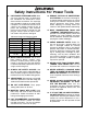
Safety Instructions For Power Tools 9. USE PROPER EXTENSION CORD. Make sure your extension cord is in good condition. Conductor size should be in accordance with the chart below. The amperage rating should be listed on the motor or tool nameplate. An undersized cord will cause a drop in line voltage resulting in loss of power and overheating. Your extension cord must also contain a ground wire and plug pin. Always repair or replace extension cords if they become damaged.
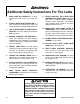
Additional Safety Instructions For The Lathe 1. MAKE SURE ALL GUARDS are in place and that the Lathe sits on a flat, stable surface. 2. ALWAYS WEAR EYE PROTECTION or a face shield when operating the Lathe. All safety equipment should be ANSI approved. 3. USE A RESPIRATOR TO AVOID INHAILING DUST. All safety equipment should be ANSI approved. 4.
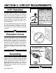
SECTION 2: CIRCUIT REQUIREMENTS 110V Operation The Model G5979 is wired for 110V operation only. The 1⁄2 H.P. motor will safely draw 4 amps at 110V. If you operate this machine on any circuit that is already close to its capacity, it might blow a fuse or trip a circuit breaker. However, if an unusual load does not exist and a power failure still occurs, contact a qualified electrician or our service department. A 15 amp dedicated circuit should be used with this wood lathe.
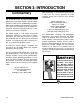
SECTION 3: INTRODUCTION Commentary We are proud to offer the Grizzly Model G5979 Wood Lathe. The Model G5979 is part of a growing Grizzly family of fine woodworking machinery. When used according to the guidelines set forth in this manual, you can expect years of trouble-free, enjoyable operation and proof of Grizzly’s commitment to customer satisfaction. The Model G5979 is a 10 speed, swivel-head wood lathe capable of a wide variety of turning operations.
Unpacking The Model G5979 is shipped from the manufacturer in a carefully packed carton. If you discover the machine is damaged after you’ve signed for delivery, immediately call Customer Service for advice. When you are completely satisfied with the condition of your shipment, you should inventory its parts in the next section. If moving this machine up or down stairs, the machine must be dismantled and moved in smaller pieces.
Piece Inventory After all the parts have been removed from the carton, you should have: • • • • • • • • • • • • • • • Lathe Unit Extension Bed Rear Legs (2) Front Legs (2) Long Leg Supports (2) Top Leg Plates (2) 4" Faceplate Live Center Spur Center Lock Handle Headstock Lock Handle (w/Spring and Cap Screw) 3, 4, 6 and 8mm Allen® Wrenches Push Rod 32mm Open End Wrench (2) Hardware Bag - M8-1.25 x 10 Carriage Bolts (24) - M8-1.25 Hex Bolts (32) - M8 Flat Washer (24) - M8-1.
Hardware Recognition Chart Wing Nut ⁄ '' 58 10 Button Head Screw Flange Bolt ⁄ '' 7 16 2 ⁄ '' 12 23⁄4'' 3 WASH S WA H ASH W ASHE ASHE 8mm ASHE ASHE R DIA DIA ER ⁄ '' 5 16 R DIA ⁄ '' 14 6mm ASHE 21⁄4'' 10mm R DIA MET LINES ARE 1⁄16'' INCH APART LINES ARE 1MM APART 2 R DIA MET 1 ⁄ '' 34 4mm MET G5979 Wood Lathe 11⁄2'' DI ER A TE ME R 16mm ⁄ '' ⁄ '' ⁄ '' ⁄ '' ⁄ '' 1'' 11⁄4'' 5 16 7 16 9 16 34 78 MET 12mm '' '' '' '' ⁄ '' 38 METE 10mm ⁄ ⁄ ⁄ ⁄ 14 38 12 58 ETER
Clean Up The unpainted surfaces are coated with a waxy oil to protect them from corrosion during shipment. Remove this protective coating with a solvent cleaner or citrus-based degreaser such as Grizzly’s G7895 Degreaser. Avoid chlorine-based solvents as they may damage painted surfaces should they come in contact. Always follow the usage instructions on the product you choose for clean up. Do not use gasoline or other petroleum-based solvents.
SECTION 4: ASSEMBLY Stand Beginning Assembly ! Disconnect power to the machine when performing any maintenance, assembly or adjustments. Failure to do this may result in serious personal injury. Keep loose clothing rolled up and out of the way of machinery and keep hair pulled back. 1. Attach a front and rear vertical leg to the top plate using the 1⁄4"-20 x 3⁄8" carriage bolts, 1⁄4" flat washers and 1⁄4" nuts. Position the top plate so that it fits inside the legs. 2.
Lathe To Stand Do not attempt to lift the lathe onto the stand by yourself. Seek the assistance of another person. 1. Carefully place the lathe unit on the stand with the help of another person. Inspect the stand to make sure all the braces and legs are still secure. 2. Align the mounting hole in the top plates with those on each end of the bed casting. 3. Attach the lathe unit to the stand using the M8-1.25 x 35 cap screws, M8 flat washers and M8-1.25 nuts as shown in Figure 5.
Headstock Lock 2. Press it into the headstock spindle. The headstock can be locked into position using the supplied locking handle. To install this handle: 1. Locate the handle, spring and special screw. 2. Slide the spring over the special screw. Push the screw through the locking handle and thread it into the locking clamp located on the side of the headstock. 3. The locking handle is designed so that it can be tightened down and then turned out of the way of the operator.
Faceplate Extension Bed The faceplate is used when turning plates, bowls and vases. The headstock spur must be removed before installing the faceplate. To install the faceplate: The extension bed mounts to the left hand side of the main lathe bed. To attach the extension bed: 1. 2. Remove the headstock spur using the push rod. Using two wrenches, thread on and tighten the faceplate/workpiece assembly onto the threaded spindle. Be sure to secure the faceplate tightly with two wrenches. Figure 10.
SECTION 5: ADJUSTMENTS ! Disconnect power to the machine when performing any maintenance, assembly or adjustments. Failure to do this may result in serious personal injury. Keep loose clothing rolled up and out of the way of machinery and keep hair pulled back. Wear safety glasses during the entire adjustment process. Failure to comply may result in serious personal injury.
Tool Rest The tool rest can be used with or without the extension arm. To adjust the tool rest: 1. To adjust the main base along the bed, loosen the lock lever and slide into the desired position. Retighten the lock lever. 2. When using the extension arm, make the necessary adjustments using the lock levers and adjusting the extension arm. Re-tighten the lock levers. 3. Make sure there is adequate clearance between the workpiece and the tool rest.
SECTION 5: OPERATIONS Test Run The speed control lever can be turned to one of ten fixed speeds. To set the speed: 1. Turn the lathe ON. Make sure that your finger is poised on the STOP button, just in case there is a problem. The lathe should run smoothly, with little or no vibration or rubbing noises. Strange or unnatural noises should be investigated and corrected before operating the machine further.
Spindle Turning 3. Line up the center of the spur center with the center mark on the end of the workpiece. While supporting the workpiece, slide the tailstock close to the end of the workpiece and lock it into place. 4. Line up the live center with the center mark on the other end of the workpiece. Turn the handwheel to press the point of the live center into the workpiece. 5. Lock the tailstock in place. To mount a workpiece between centers: 1.
Faceplate Turning Faceplate turning projects fall into two categories: those that extend below the level of the lathe/extension bed and those that do not. If your project will rotate below the level of the lathe/extension bed, you will need to rotate the headstock to the 60° or 90° positions (discussed further in Adjustments section). But if your project does not extend below the lathe/extension bed, it is safest to rotate the headstock 180° so the project will rotate over the extension bed.
SECTION 7: MAINTENANCE Rust ! Disconnect power to the machine when performing any maintenance, assembly or adjustments. Failure to do this may result in serious personal injury. Keep loose clothing rolled up and out of the way of machinery and keep hair pulled back. Wear safety glasses during the entire maintenance process. Failure to comply may result in serious personal injury. The nonpainted surfaces on the Model G5979 should be protected against rust and pitting.
SECTION 8: CLOSURE The following pages contain general machine data, parts diagrams/lists, a troubleshooting guide and Warranty/Return information for your Model G5979. If you need parts or help in assembling your machine, or if you need operational information, we encourage you to call our Service Department. Our trained service technicians will be glad to help you.
MACHINE DATA SHEET Customer Service #: (570) 546-9663 • To Order Call: (800) 523-4777 • Fax #: (800) 438-5901 GRIZZLY MODEL G5979 SWIVEL HEAD WOOD LATHE Design Type ....................................................................................................Bench Model Overall Dimensions: Height ......................................................................................................................44'' Length .............................................................................
63 16 26 71 28 15 30 52 27 12 Lube Fitting 32 10 31 34 35 33 8 68 18 7A 9 17A 59 11 53 57A 69 1 20 53-1 19 13 25 58 22 23 21-1 66 65-1 64 5 21 6A 4 44A 43 37 24-2 24A 39 38 3 24-3 37 36 24-1 2 41 46 45 50 40 41 55 47 37 42 51 44A 43 48 49 48-1
62 54-6 61 62 61 60 62 54-1 61 56 60 54-4 54-1 54-5 54-3 54-6
Ref# Part# Description Ref# Part# Description 01 P5979001 HEADSTOCK 39 P5979039 TOOL REST BODY 02 P5979002 DRIVE CENTER 40 P5979040 ECCENTRIC ROD 03 P5979003 DISC 41 PR08M EXT RETAINING RING 19MM 04 P5979004 SPINDLE 42 P5979042 SPECIAL SCREW 05 PK18M KEY 4 X 4 X 82 43 P5979043 CLAMP 06A P5979006A BALL BEARING 80205Z 44A P5979044A HEX NUT M18-2.
WARRANTY AND RETURNS Grizzly Industrial, Inc. warrants every product it sells for a period of 1 year to the original purchaser from the date of purchase. This warranty does not apply to defects due directly or indirectly to misuse, abuse, negligence, accidents, repairs or alterations or lack of maintenance.
WARRANTY CARD Name ____________________________________________________________________________________ Street ____________________________________________________________________________________ City ______________________________________________________________State________Zip_________ Phone Number_______________________E-Mail_______________________FAX________________________ MODEL # G5979 Wood Lathe Order #______________________________________________ The following information is given on a voluntary ba
FOLD ALONG DOTTED LINE Place Stamp Here GRIZZLY INDUSTRIAL, INC. P.O.