ULTIMATE SERIES JOINTERS MODELS G9859 / G9860 / G9860ZX / G9861 INSTRUCTION MANUAL COPYRIGHT © MARCH, 2002 BY GRIZZLY INDUSTRIAL, INC. WARNING: NO PORTION OF THIS MANUAL MAY BE REPRODUCED IN ANY SHAPE OR FORM WITHOUT THE WRITTEN APPROVAL OF GRIZZLY INDUSTRIAL, INC. PRINTED IN TAIWAN.
WARNING Some dust created by power sanding, sawing, grinding, drilling, and other construction activities contains chemicals known to the State of California to cause cancer, birth defects or other reproductive harm. Some examples of these chemicals are: • Lead from lead-based paints. • Crystalline silica from bricks, cement, and other masonry products. • Arsenic and chromium from chemically treated lumber. Your risk from these exposures varies, depending on how often you do this type of work.
Table Of Contents PAGE 1. SAFETY SAFETY INSTRUCTIONS FOR POWER TOOLS ..............................................2-3 ADDITIONAL SAFETY INSTRUCTIONS FOR JOINTERS ....................................4 2. CIRCUIT REQUIREMENTS 220V OPERATION ..................................................................................................5 CIRCUIT LOAD ........................................................................................................5 GROUNDING ...........................................
SECTION 1: SAFETY For Your Own Safety Read Instruction Manual Before Operating This Equipment The purpose of safety symbols is to attract your attention to possible hazardous conditions. This manual uses a series of symbols and signal words which are intended to convey the level of importance of the safety messages. The progression of symbols is described below. Remember that safety messages by themselves do not eliminate danger and are not a substitute for proper accident prevention measures.
Safety Instructions For Power Tools 9. USE PROPER EXTENSION CORD. Make sure your extension cord is in good condition. Conductor size should be in accordance with the chart below. The amperage rating should be listed on the motor or tool nameplate. An undersized cord will cause a drop in line voltage resulting in loss of power and overheating. Your extension cord must also contain a ground wire and plug pin. Always repair or replace extension cords if they become damaged.
Additional Safety Instructions For Jointers 9. JOINT WITH THE GRAIN. Jointing against the grain is dangerous and could produce chatter or excessive chip out , which could lead to loss of control over the workpiece. 1. JOINTING SAFETY BEGINS with your lumber. Inspect your stock carefully before you feed it over the cutterhead. If you have any doubts about the stability or structural integrity of your stock, DO NOT JOINT IT! 2.
SECTION 2: CIRCUIT REQUIREMENTS 220V Operation Circuit Load The Ultimate Series Jointers have a 3 H.P., 3450 R.P.M. motor which requires a 220V single-phase circuit. The cord set enclosed does not have a plug as the style of plug you require will depend upon the type of service you currently have or plan to install. The motor will safely draw about 15 amps at 220V under load.
Grounding Extension Cords In the event of an electrical short, grounding provides electric current a path of least resistance to reduce the risk of electrical shock. This tool is equipped with an electric cord having an equipment-grounding conductor which must be properly connected to a grounding plug. The plug must be plugged into a matching outlet that is properly installed and grounded in accordance with all local codes and ordinances.
SECTION 3: INTRODUCTION Commentary We are proud to offer the Ultimate Series Jointers. These machines are part of a growing Grizzly family of fine woodworking machinery. When used according to the guidelines set forth in this manual, you can expect years of trouble-free, enjoyable operation and proof of Grizzly’s commitment to customer satisfaction. The Ultimate Series Jointers all feature 3 H.P. TEFC motors.
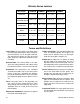
Ultimate Series Jointers Description G9859 G9860 G9860ZX G9861 Table Size 8 1⁄2" x 73 3⁄8" 12 1⁄2" x 80" 12 1⁄2" x 80" 14 1⁄4" x 79 3⁄4" Cutterhead Speed 5900 R.P.M. 5900 R.P.M. 5900 R.P.M. 5900 R.P.M. Cutterhead 4" Dia., 3 Knife 4" Dia., 3 Knife Spiral Cutterhead 4" Dia., 3 Knife Motor 3 H.P./1 PH. 3 H.P./1 PH. 3 H.P./1 PH. 3 H.P./1 PH. Fence Size 4 3⁄4" x 39 1⁄4" 4 3⁄4" x 39 1⁄4" 4 3⁄4" x 39 1⁄4" 4 3⁄4" x 39 3⁄8" Weight 900 lbs. 1080 lbs. 1080 lbs. 1210 lbs.
Unpacking The Ultimate Series Jointers are shipped from the manufacturer in a carefully packed carton. If you discover the machine is damaged after you’ve signed for delivery, immediately call Customer Service for advice. When you are completely satisfied with the condition of your shipment, you should inventory its parts.
Clean Up The unpainted surfaces are coated with a waxy oil to protect it from corrosion during shipment. Remove this protective coating with a solvent cleaner or citrus-based degreaser such as Grizzly’s G7895 Degreaser. Avoid chlorine-based solvents as they may damage painted surfaces should they come in contact. Always follow the usage instructions on the product you choose for clean up. Site Considerations FLOOR LOAD Your Ultimate Series Jointer represents a large weight load in a medium footprint.
SECTION 4: ASSEMBLY Beginning Assembly ! Disconnect power to the machine when performing any maintenance, assembly or adjustments. Failure to do this may result in serious personal injury. Keep loose clothing rolled up and out of the way of machinery and keep hair pulled back. Wear safety glasses during the entire assembly process. Failure to comply may result in serious personal injury. Some metal parts may have sharp edges on them after they are formed.
Cutterhead Guard Installed Key The cutterhead guard spring tension comes preset from the factory. To install the cutterhead guard: 1. Loosen the black plastic knob shown in Figure 6. 2. Slide the cutterhead assembly post into the slot shown in Figure 6. 3. Tighten the black plastic knob that was loosened in Step 1. Figure 4. Properly installed key. 3. Carefully lift the fence assembly onto the fence base support. Make sure that the key is fully seated into the key way.
Pedestal Switch Your jointer comes with a pedestal mounted magnetic switch for safety and convenience. Simply bolt the pedestal to the four mounting holes on the back side of the stand with (4) M10-1.5 x 25 cap screws and (4) M10 flat washers as shown in Figure 7A & 7B. Figure 7A. Mounting the pedestal switch. Figure 7B. Mounted pedestal switch.
SECTION 5: ADJUSTMENTS General ! Disconnect power to the machine when performing any maintenance, assembly or adjustments. Failure to do this may result in serious personal injury. Keep loose clothing rolled up and out of the way of machinery and keep hair pulled back. Wear safety glasses during the entire adjustment process. Failure to comply may result in serious personal injury. Table Lock -14- Always lock the table with the table lock before using the jointer.
4. Adjust the screws below each end of the knife until both feet of the gauge rest flush and evenly on the outfeed table and the knife edge is just touching the bottom of the gauge. Securely tighten each gib bolt. The gauge will set the knives at a uniform protrusion above the cutterhead. The knife height should vary no more than .002"-.003" across the length of the cutterhead.
Spiral Cutterhead The Model G9860ZX is equipped with a spiral cutterhead. The indexed square carbide cutters have four separate cutting surfaces that can be rotated as needed. If one of the cutters becomes damaged or dull, rotate the cutter to reveal the fresh cutting surface. Each edge of the indexed cutter is marked for easy identification. When an indexed cutter needs to be replaced, please order part #H2334 from the current Grizzly catalog. 2.
Infeed Table To adjust the infeed table: 1. The infeed table can be adjusted the same way as the outfeed table. Loosen the infeed table lock knob in the center of the handwheel. 2. Place a straightedge on the outfeed table so it hangs over the infeed table. Turn the cutterhead so that the knives are NOT touching the straightedge. 3. Loosen the infeed table lock knob. Raise the infeed table until it just touches the straightedge as shown in Figure 13. Tighten the table lock knob. Figure 14.
45° Fence Stop 1. Place a 45° gauge on the outfeed table fairly close to the cutterhead as shown in Figure 16. 45° Stop Figure 17. Setting the 45° stop. Figure 16. Using a 45° gauge to align fence. 2. While holding the fence adjusting handle, loosen the angle setting lock knob and the checknut on the 45° stop screw as shown in Figure 17. Turn the stop screw against the sliding bracket until the fence contacts the edge of the 45° gauge evenly. 3.
SECTION 6: OPERATIONS Test Run ! Disconnect power to the machine when performing any maintenance, assembly or adjustments. Failure to do this may result in serious personal injury. Keep loose clothing rolled up and out of the way of machinery and keep hair pulled back. Wear safety glasses during the entire operation process. Failure to comply may result in serious personal injury. Stock Inspection If the stock has large or loose knots, consider finding another workpiece.
Edge Jointing Beveling The purpose of edge jointing is to produce a finished, flat-edged surface that is suitable for joinery or finishing. Jointing is also a necessary step prior to ripping stock to width on a table saw or radial arm saw. Beveling an edge is essentially the same operation as edge jointing, except that the fence is tilted to a specified angle. Use extra care to ensure that the edge makes solid contact with the infeed and outfeed tables at all times. 1.
Surface Planing The purpose of planing on a jointer is to produce one flat surface. The theory behind this is that once you have one flat surface on a board, the board can then more readily be milled to precise, flat dimensions on a thickness planer. It is nearly impossible to surface plane both sides of a board effectively because the two surfaced sides will retain any warps, cups, or twists. 1. Inspect your lumber for soundness and grain direction. 2.
SECTION 7: MAINTENANCE Tables Disconnect power to the machine when performing any maintenance, assembly or adjustments. Failure to do this may result in serious personal injury. ! Keep loose clothing rolled up and out of the way of machinery and keep hair pulled back. Wear safety glasses during the entire maintenance process. Failure to comply may result in serious personal injury. General Regular periodic maintenance on your Ultimate Series Jointer will ensure its optimum performance.
SECTION 8: CLOSURE The following pages contain general machine data, parts diagrams/lists, a troubleshooting guide and Warranty/Return information for your Ultimate Series Jointer. If you need parts or help in assembling your machine, or if you need operational information, we encourage you to call our Service Department. Our trained service technicians will be glad to help you.
TROUBLESHOOTING CORRECTIVE ACTION SYMPTOM POSSIBLE CAUSE Motor will not start. 1. 2. 1. Low voltage. Open circuit in motor or loose 2. connections. Check power line for proper voltage. Inspect all lead connections on motor for loose or open connections. Motor will not start; fuses or 1. circuit breakers blow. 2. Short circuit in line cord or plug. 1. Short circuit in motor or loose 2. connections. Incorrect fuses or circuit break- 3. ers in power line.
MACHINE DATA SHEET Customer Service #: (570) 546-9663 • To Order Call: (800) 523-4777 • Fax #: (800) 438-5901 8" JOINTER MODEL G9859 Design Type ....................................................................................................Floor Model Overall Dimensions: Table Size ..................................................................................................733⁄8'' x 81⁄2'' Height (from Floor to Table) ...............................................................................
030 023 010 034 009 031 033 023 001 004 005 011 016 015 013 PO W ER 014 023 OP 50 017 ST 00 003 MIN 012 026 027 G9859 8" JOINTER
109 Badey e's Blue Be aring C 104 110 6305 121 113 119 706 705 708 101 104 Badey 703 709 116 704 115 114 Belt Co. B l ue R ay Belt Co. 702 BlueR ay 701 710 112 111 102 110 103 707 120 108 105 Blue Be aring C 6305 o. e's o.
G9859 8" JOINTER 217 216 219 214 218 215 207 201 202 203 210 211 206 213 204 205 212 209 221 208 220 602 607 018 606 603 605 601 604 002 019 020 021 022
511 510 509 502 520 UP 521 512 D0W N 516 518 519 501 517 508 506 522 505 515 513 514 523 504 503 507 G9859 8" JOINTER
403 712 407 406 405 006 404 402 029 307 028 401 713 714 715 024 025 716 301 023 032 024 303 304 302 305 008 025 308 306 309 007 G9859 8" JOINTER
Ref# Part# Description Ref# Part# Description 001 P9859001 BASE 117 PSS09M SET SCREW M8-1.
Ref# Part# Description Ref# Part# Description 509 P9859509 SPECIAL RETAINER RING 605 P9859605 PIN 510 P9859510 SPECIAL WASHER 606 PSS02M SET SCREW M6-1.0 X 6 511 P9859511 LOCK KNOB 607 P9859607 SPRING 512 P9859512 HANDWHEEL KNOB 701 P9859701 MOTOR 3 H.P. 513 PSB47M CAP SCREW M10-1.5 X 40 702 P9859702 PULLEY 514 PN03M HEX NUT M8-1.25 703 PK54M KEY 7 X 7 X 45 515 PSS04M SET SCREW M6-1.
MACHINE DATA SHEET Customer Service #: (570) 546-9663 • To Order Call: (800) 523-4777 • Fax #: (800) 438-5901 12" JOINTER MODEL G9860/G9860ZX Design Type ....................................................................................................Floor Model Overall Dimensions: Table Size ....................................................................................................80'' x 121⁄2'' Height (from Floor to Table) ......................................................................
031 032 035 031 010 034 009 030 033 023 001 004 005 011 016 015 013 PO W ER 014 023 50 017 ST OP 00 003 MIN 012 026 027 G9860 12" JOINTER
705 Badey 703 709 118 704 117 116 702 Co. 701 706 708 104 Co. Belt 803 112 710 122 102 707 101 103 110 Belt B l ue R ay 802 Badey 115 121 113 114 BlueR ay 801 G9860ZX Spiral Cutterhead 111 109 e's Blue Be aring C 104 110 6305 108 105 Blue Be aring C 6305 o. e's o.
G9860 12" JOINTER 217 216 219 214 218 215 207 201 202 203 210 211 206 213 204 205 212 209 221 208 220 602 607 018 606 603 605 601 604 002 019 020 021 022
511 510 509 502 520 UP 521 512 D0W N 516 518 519 501 517 508 506 522 505 515 513 514 523 504 503 507 G9860 12" JOINTER
3 712 006 404 505 402 029 302 028 401 713 714 715 024 025 716 301 024 307 304 306 305 008 309 025 308 310 303 311 007 G9860 12" JOINTER
Ref# Part# Description Ref# Part# Description 001 P9860001 BASE 116 P9859119 002 P9860002 FENCE SEAT 117 PW04M FLAT WASHER M10 003 P9859003 TABLE SUPPORT 118 PB65 HEX BOLT 3⁄8"-16 X 5⁄8" 004 P9859004 TABLE LIFTING ARM 119 PSS09M SET SCREW M8-1.25 X 20 005 P9859005 TABLE SUPPORT 120 P9859118 SPECIAL HEX NUT 006 P9859006 FRONT HOUSING 121 PS11M PHLP HD SCR M6-1.
Ref# Part# Description Ref# Part# Description 507 P9859507 LIFT ROD 602 P9859602 COLLAR 508 P9859508 SPECIAL RETAINER RING 603 P9859603 HANDLE 509 P9859509 SPECIAL RETAINER RING 604 P9859604 BRAKE CASING 510 P9859510 SPECIAL WASHER 605 P9859605 PIN 511 P9859511 LOCK KNOB 606 PSS02M SET SCREW M6-1.0 X 6 512 P9859512 HANDWHEEL KNOB 607 P9859607 SPRING 513 PSB47M CAP SCREW M10-1.5 X 40 701 P9859701 MOTOR 3 H.P. 514 PN03M HEX NUT M8-1.
MACHINE DATA SHEET Customer Service #: (570) 546-9663 • To Order Call: (800) 523-4777 • Fax #: (800) 438-5901 14" JOINTER MODEL G9861 Design Type ....................................................................................................Floor Model Overall Dimensions: Table Size ................................................................................................793⁄4'' x 141⁄4'' Height (from Floor to Table) ...............................................................................
032 020 036 032 018 035 006 021 034 012 001 019 004 005 013 014 011 PO W ER 015 012 50 012 ST OP 00 003 MIN 010 016 017 G9861 14" JOINTER
111 109 Badey e's Blue Be aring C 104 110 6305 121 113 119 706 705 104 Badey 703 116 704 115 114 709 108 105 Belt Co. BlueR ay Belt Co. 702 BlueR ay 701 112 710 122 102 708 101 103 707 120 110 Blue Be aring C 6305 o. e's o.
G9861 14" JOINTER 217 216 219 214 218 215 207 201 202 203 210 211 206 213 204 205 212 209 221 208 220 037 602 607 022 606 603 605 601 604 002 023 028 029 030
511 510 509 502 520 UP 521 512 D0W N 516 518 519 501 517 508 506 522 505 515 513 514 523 504 503 507 G9861 14" JOINTER
403 712 007 404 405 402 027 304 026 401 713 714 715 024 031 716 301 311 312 025 313 310 033 314 024 307 302 303 306 008 025 308 305 309 009 G9861 14" JOINTER
Ref# Part# Description Ref# Part# Description 001 P9861001 BASE 114 P9859119 002 P9861002 FENCE SEAT 115 PW04M FLAT WASHER M10 003 P9859003 TABLE SUPPORT 116 PB65 HEX BOLT 3⁄8"-16 X 5⁄8" 004 P9859005 TABLE SUPPORT 117 PSS09M SET SCREW M8-1.
Ref# Part# Description Ref# Part# Description 503 P9859503 GEAR 602 P9859602 COLLAR 504 P9859504 COLLAR 603 P9859603 HANDLE 505 P9859505 LIFT ROD 604 P9859604 BRAKE CASING 506 P9859506 GEAR 605 P9859605 PIN 507 P9859507 LIFT ROD 606 PSS02M SET SCREW M6-1.0 X 6 508 P9859508 SPECIAL RETAINER RING 607 P9859607 SPRING 509 P9859509 SPECIAL RETAINER RING 701 P9859701 MOTOR 3 H.P.
NOTES Ultimate Series Jointers -49-
WARRANTY AND RETURNS Grizzly Industrial, Inc. warrants every product it sells for a period of 1 year to the original purchaser from the date of purchase. This warranty does not apply to defects due directly or indirectly to misuse, abuse, negligence, accidents, repairs or alterations or lack of maintenance.
WARRANTY CARD Name ____________________________________________________________________________________ Street ____________________________________________________________________________________ City ______________________________________________________________State________Zip_________ Phone Number_______________________E-Mail_______________________FAX________________________ MODEL #____________________________ Serial #______________________________________________ The following information is given on a
FOLD ALONG DOTTED LINE Place Stamp Here GRIZZLY INDUSTRIAL, INC. P.O.