MODEL G9922 OSCILLATING SPINDLE SANDER OWNER'S Manual Copyright © 2000 By Grizzly Industrial, Inc. REVISED March, 2010 (JB) Warning: No portion of this manual may be reproduced in any shape Or form without the written approval of Grizzly Industrial, inc.
This manual provides critical safety instructions on the proper setup, operation, maintenance and service of this machine/equipment. Failure to read, understand and follow the instructions given in this manual may result in serious personal injury, including amputation, electrocution or death. The owner of this machine/equipment is solely responsible for its safe use.
Table of Contents INTRODUCTION................................................................................................................................ 4 Foreword..................................................................................................................................... 4 Contact Info................................................................................................................................. 4 Functional Overview............................................
INTRODUCTION Foreword Functional Overview We are proud to offer the Model G9922 Oscillating Spindle Sander. This machine is part of a growing Grizzly family of fine woodworking machinery. When used according to the guidelines set forth in this manual, you can expect years of trouble-free, enjoyable operation and proof of Grizzly’s commitment to customer satisfaction. An oscillating spindle sander is used to sand the edges of contoured or irregularly shaped workpieces.
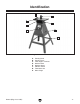
Identification A H B C G D F E Figure 1. Identification. A. Sanding Table B. Sanding Drum C. Table Angle Lock Knob D. Machine Base E. Machine Stand F. ON/OFF Switch G. Table Miter Slot H. Miter Gauge G9922 (Mfg.
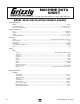
MACHINE DATA SHEET Customer service #: (570) 546-9663 · to order Call: (800) 523-4777 · Fax #: (800) 438-5901 MODEL G9922 OSCILLATING SPINDLE SANDER Product Dimensions: Weight................................................................................................................................................................ 86 lbs. length/Width/height....................................................................................................................... 26 x 26 x 39-1/2 in.
Spindle Info spindle diameters........................................................................................................................................ 2 in. spindle lengths..................................................................................................................................... 5-1/2 in. spindle speed....................................................................................................................................3450 rpM spindle oscillations......
SECTION 1: SAFETY For Your Own Safety, Read Instruction Manual Before Operating this Machine The purpose of safety symbols is to attract your attention to possible hazardous conditions. This manual uses a series of symbols and signal words intended to convey the level of importance of the safety messages. The progression of symbols is described below. Remember that safety messages by themselves do not eliminate danger and are not a substitute for proper accident prevention measures.
Safety Instructions for Machinery 7. ONLY ALLOW TRAINED AND PROPERLY SUPERVISED PERSONNEL TO OPERATE MACHINERY. Make sure operation instructions are safe and clearly understood. 8. KEEP CHILDREN/VISITORS AWAY. Keep all children and visitors away from machinery. When machine is not in use, disconnect it from power, lock it out, or disable the switch to make it difficult for unauthorized people to start the machine. 9. UNATTENDED OPERATION.
Additional Safety Instructions For Spindle Sanders 1. Be aware of SPINDLE rotation when sanding. 2. Keep fingertips away from the moving spindle. Serious injury could result if skin contacts abrasives or moving parts. 3. 6. If there is any doubt as to the stability or integrity of the material to be sanded, don’t sand it. 7. Do not operate sander with a damaged or badly worn sanding sleeve. Never use excessive force when sanding.
SECTION 2: CIRCUIT REQUIREMENTS 110V Operation Power Connection Device The Model G9922 comes with a 5-15 plug, similar to Figure 2, to connect the machine to power. Grounding Prong is Longest of the Three Prongs Serious personal injury could occur if you connect the machine to power before completing the setup process. DO NOT connect the machine to the power until instructed later in this manual.
SECTION 3: SETUP Setup Safety This machine presents serious injury hazards to untrained users. Read through this entire manual to become familiar with the controls and operations before starting the machine! Wear safety glasses during the entire setup process! This machine and its components are heavy. Get lifting help or use power lifting equipment such as a forklift to move heavy items.
Inventory A C B The following is a description of the main components shipped with your machine. Lay the components out to inventory them. Note: If you can't find an item on this list, check the mounting location on the machine or examine the packaging materials carefully. Occasionally we pre-install certain components for shipping purposes. Box Contents: (Figures 3 & 4) Qty A. Miter Gauge................................................. 1 B. Open End Wrench 14/17mm....................... 1 C.
Hardware Recognition Chart -14- G9922 (Mfg.
Clean Up The unpainted surfaces are coated with a waxy oil to prevent corrosion during shipment. Remove this protective coating with a solvent cleaner or degreaser, such as shown in Figure 5. For thorough cleaning, some parts must be removed. For optimum performance from your machine, clean all moving parts or sliding contact surfaces. Avoid chlorine-based solvents, such as acetone or brake parts cleaner that may damage painted surfaces.
Mounting to Shop Floor Although not required, you may choose to mount your new machine to the floor. Because this is an optional step and floor materials may vary, floor mounting hardware is not included. Generally, you can either bolt your machine to the floor or mount it on machine mounts. Both options are described below. Whichever option you choose, it is necessary to level your machine with a precision level.
Assembly Assembly for the Model G9922 consists of putting together the machine stand, attaching the machine to the stand, then inserting the sanding spindle. Lower Brace Upper Brace To assemble the machine: x4 1. Lay out two legs, one upper brace and one lower brace, then connect them using four M8-1.25 x 16 carriage bolts, four 10mm flat washers, four 8mm lock washers, and four M8-1.25 hex nuts, as shown in Figure 9. Do not yet fully tighten the nuts. Upper Brace x4 Lower Brace Legs Figure 9.
Note: The next step involves mounting feet on the machine. If you plan to mount your machine to the floor, skip ahead to Step 6. Otherwise, continue with Step 5, below. 5. On each of the four legs, install a rubber foot by removing the hex nut and washers from the foot assembly, inserting the foot into the hole at the bottom of the leg, then securing the foot with the removed washers and nut, as shown in Figure 12. 7.
10. Place the sanding drum into the spindle and thread it by turning it counterclockwise (Figure 16). Figure 16. Inserting sanding drum. 11. To easily access the spindle nut, move the dust cover out of the way by removing the two hex bolts that secure it to the machine base (Figure 17). 12. Secure the sanding drum into the spindle by holding the spindle stationary with a 17mm wrench while tightening the drum with a 19mm wrench, as shown in Figure 18. Figure 18. Securing sanding drum. Hex Bolt Figure 17.
Test Run Once the assembly is complete, test run your machine to make sure it runs properly and is ready for regular operation. 5. Turn the machine OFF. 6. Remove the switch disabling key, as shown in Figure 19. The test run consists of verifying the following: 1) The motor powers up and runs correctly, and 2) the safety disabling mechanism on the switch works correctly.
SECTION 4: OPERATIONS Operation Safety Basic Controls Use the descriptions and figures below to become familiar with the basic controls of your machine. To reduce the risk of serious injury when using this machine, read and understand this entire manual before beginning any operations. Damage to your eyes and lungs could result from using this machine without proper protective gear. Always wear safety glasses and a respirator when operating this machine. ON/OFF Switch: Turns machine ON/OFF.
Table Tilt 0º Table Stop The table on the Model G9922 can be tilted up to 45° for sanding beveled edges. The Model G9922 has a 0° table stop that lets you easily set the table tilt back to 0º for sanding square edges. To tilt the table: 1. DISCONNECT SANDER FROM POWER! 2. Loosen the two lock knobs, located on each side of the table tilt assembly (Figure 22). To set the 0° stop: 1. DISCONNECT SANDER FROM POWER! 2. Loosen the jam nut and turn the stop bolt several turns clockwise (Figure 24).
Contour Sanding Miter Gauge 1. DISCONNECT SANDER FROM POWER! The Model G9922 includes a miter gauge that can be used for sanding miter-cut edges at angles from -60° to 60º. 2. Adjust the table tilt, if desired. To use the miter gauge: To sand a workpiece: 3. 4. Ensure that the spindle hex nut is secured tightly and that the work area is free of obstructions and obstacles. Connect the sander to power, turn ON the spindle sander and allow it to reach full speed. 5.
6. Hold the workpiece flat on the table and against the miter gauge, and begin sliding the gauge back and forth in the slot on the table. At the same time, gradually move the workpiece into the sanding drum (Figure 28). Sanding Sleeve The sanding sleeves on the Model G9922 can be replaced when they become worn or damaged. To replace sanding sleeves: 1. DISCONNECT SANDER FROM POWER! 2. Use a 19mm wrench on the sanding drum base nut to keep the spindle from turning (Figure 29). Sanding Drum Figure 28.
ACCESSORIES SECTION 5: ACCESSORIES T20501—Face Shield, 4" Crown, Clear T20502—Face Shield, 7" Crown, Clear T20448—Economy Clear Safety Glasses T20452—"Kirova" Anti-Reflective Glasses T20456—"Dakura" Clear Safety Glasses H0736—Shop Fox® Safety Glasses These glasses meet ANSI Z87.1-2003 specifications. Buy extras for visitors or employees.
G7314—Heavy-Duty SHOP FOX® Mobile Base Make your machine mobile with this popular patented mobile base. The unique outrigger type supports increase stability and lower machine height. This heavy duty mobile base is rated for up to a 600 lb. capacity. 3-Pack Sanding Sleeves H1474—2" x 51⁄4" 60 Grit H1475—2" x 51⁄4" 80 Grit H1476—2" x 51⁄4" 100 Grit H1477—2" x 51⁄4" 120 Grit H1478—2" x 51⁄4" 150 Grit These aluminum oxide sanding sleeves are a direct replacement for the Model G9922 Oscillating Spindle Sander.
SECTION 6: MAINTENANCE Unpainted Cast Iron Always disconnect power to the machine before performing maintenance. Failure to do this may result in serious personal injury. Schedule Protect the unpainted cast iron surfaces on the table by wiping the table clean after every use— this ensures moisture from wood dust does not remain on bare metal surfaces. Keep tables rust-free with regular applications of products like G96® Gun Treatment, SLIPIT®, or Boeshield® T-9.
Ball Oiler (Figure 39) Lubricate the ball oilers after every 2 hours of use. Use a manual oiler (oil can) filled with ISO 68 or SAE 30W non-detergent oil. Make sure to clean the outside of the ball oiler before and after each use to keep out contaminants. To lubricate the ball oiler: 1. DISCONNECT SANDER FROM POWER! 2. Look towards the spindle shaft behind the rubber dust cover (Figure 39). —If you can see the ball oiler, skip ahead to Step 4. Ball Oiler Figure 39.
SECTION 7: SERVICE Review the troubleshooting and procedures in this section to fix or adjust your machine if a problem develops. If you need replacement parts or you are unsure of your repair skills, then feel free to call our Technical Support at (570) 546-9663. Troubleshooting Motor & Electrical Symptom Motor will not start. Possible Cause 1. Disabling key removed. 2. Open circuit in motor or loose connections. 3. ON/OFF switch at fault. Possible Solution 1. Insert disabling key. 2.
Wiring Diagram ON/OFF Switch (Viewed from behind) View this page in color at www.grizzly.com. MOTOR 110V Ground V1 U1 U2 U1 Z2W2 V1 U2 V2 Z1W1 Ground Start Capacitor 250MFD 125VAC Ground Start Capacitor 250MFD 125VAC WARNING! SHOCK HAZARD! Black Hot Disconnect power before working on wiring. White Neutral 110 VAC 5-15 Plug Green Ground Figure 40. Motor wiring. -30- Figure 41. ON/OFF Switch wiring. G9922 (Mfg.
Parts Breakdown 38 36 35 87 30 43 41 42 34 44 84 83 37 33 86-1 86 18 40 82 10 85 81 39 59 78 51 52 32 31 41 10 78 51 52 73 80 52 30 29, 29V2* 27 77 79 72 71 48 76 41 30 45 74 28, 28V2* 46 24 97 26, 26V2* 70 51 52 22 23 21, 21V2* 20 69 39 68 54 67 53 64 19 16 18 17 98 41 12 8 11 55, 55V2* 6 7 5 9 10 13 14 56 52 51 50 62 60 1A-5 1A-4 1A-2 1A-3 1A-1 61 1A (Version 2 Fits Models Produced After 01/06) 59 58 57 1-5 1-4 1-2 1-3 1-1 * V2 Fits Models Produced
Parts List REF PART # DESCRIPTION REF PART # DESCRIPTION 5 6 7 8 9 10 11 12 13 14 16 17 18 19 20 21 21V2 22 23 24 26 26V2 27 28 28V2 29 29V2 30 31 32 33 34 35 36 37 38 39 40 41 42 43 44 45 46 48 50 51 52 53 54 55 FLAT KEY 100 x 356 x 2 CONNECTION PLATE WORM GEAR SHAFT PINION GEAR END COVER OF WORM GEAR HEX BOLT M5-.8 X 10 HEX BOLT M5-.8 X 25 CONNECTING BAR FLANGE BUSHING SPECIAL SCREW 110 x 88 x 78 HEX NUT M5-.8 HEX NUT M8-1.
WARRANTY CARD Name _____________________________________________________________________________ Street _____________________________________________________________________________ City _______________________ State _________________________ Zip _____________________ Phone # ____________________ Email ________________________ Invoice # _________________ Model # ____________________ Order # _______________________ Serial # __________________ The following information is given on a voluntary basis.
FOLD ALONG DOTTED LINE Place Stamp Here GRIZZLY INDUSTRIAL, INC. P.O.
WARRANTY AND RETURNS WARRANTY AND RETURNS Grizzly Industrial, Inc. warrants every product it sells for a period of 1 year to the original purchaser from the date of purchase. This warranty does not apply to defects due directly or indirectly to misuse, abuse, negligence, accidents, repairs or alterations or lack of maintenance.
Buy Direct and Save with Grizzly ® – Trusted, Proven and a Great Value! ~Since 1983~ Visit Our Website Today For Current Specials! ORDER 24 HOURS A DAY! 1-800-523-4777