5" OPEN-END WIDE-BELT SANDER MODEL G9983 INSTRUCTION MANUAL COPYRIGHT © OCTOBER, 2002 BY GRIZZLY INDUSTRIAL, INC. WARNING: NO PORTION OF THIS MANUAL MAY BE REPRODUCED IN ANY SHAPE OR FORM WITHOUT THE WRITTEN APPROVAL OF GRIZZLY INDUSTRIAL, INC.
WARNING Some dust created by power sanding, sawing, grinding, drilling, and other construction activities contains chemicals known to the State of California to cause cancer, birth defects or other reproductive harm. Some examples of these chemicals are: • Lead from lead-based paints. • Crystalline silica from bricks, cement, and other masonry products. • Arsenic and chromium from chemically treated lumber. Your risk from these exposures varies, depending on how often you do this type of work.
Table Of Contents 1. 2. 3. 4. 5. 6. 7. 8. 9. PAGE SAFETY SAFETY RULES FOR POWER TOOLS ..........................................................................................2-3 SAFETY RULES FOR THE WIDE BELT SANDER ............................................................................4 INTRODUCTION ........................................................................................................................................5 CIRCUIT REQUIREMENTS ....................................
SECTION 1: SAFETY For Your Own Safety Read Instruction Manual Before Operating This Equipment The purpose of safety symbols is to attract your attention to possible hazardous conditions. This manual uses a series of symbols and signal words which are intended to convey the level of importance of the safety messages. The progression of symbols is described below. Remember that safety messages by themselves do not eliminate danger and are not a substitute for proper accident prevention measures.
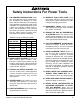
Safety Instructions For Power Tools 9. USE PROPER EXTENSION CORD. Make sure your extension cord is in good condition. Conductor size should be in accordance with the chart below. The amperage rating should be listed on the motor or tool nameplate. An undersized cord will cause a drop in line voltage resulting in loss of power and overheating. Your extension cord must also contain a ground wire and plug pin. Always repair or replace extension cords if they become damaged.
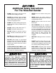
Additional Safety Instructions For The Wide-Belt Sander • DO NOT allow anyone to stand at the outfeed end when feeding your stock. • NEVER leave the machine running unattended. • DO NOT jam workpiece into the machine during operation. Firmly grasp the workpiece in both hands and ease it into the machine using light pressure. • NEVER operate the sander without an adequate dust collection system in place and operating correctly. • • DO NOT wear loose clothing while operating this machine.
SECTION 2: INTRODUCTION Read the manual before assembly and operation. Become familiar with the machine and its operation before beginning any work. Serious personal injury may result if safety or operational information is not understood or followed. We are proud to offer the Grizzly Model G9983 Wide-belt Sander. Your machine is part of a growing Grizzly family of fine woodworking machinery.
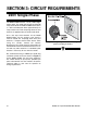
SECTION 3: CIRCUIT REQUIREMENTS 220V Single-Phase The Model G9983 features a 5 HP, 220V singlephase motor. This motor will safely draw about 30 amps under load. The Model G9983 also features a 1⁄4 HP feed motor that draws approximately 1.8 amps under load. Total amperage draw for this machine is approximately 32 amps under load. Use a 35 amp circuit breaker for the Model G9983. Make sure the wiring in your circuit is rated to handle the amperage draw from your machine.
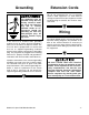
Grounding This equipment must be grounded. Verify that any existing electrical outlet and circuit you intend to plug into is actually grounded. Under no circumstances should the grounding pin from any three-pronged plug be removed. Serious injury may occur. In the event of an electrical short, grounding reduces the risk of electric shock by providing a path of least resistance to disperse electric current.
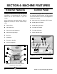
SECTION 4: MACHINE FEATURES External Features Control Panel To help you understand the set up and operation instructions, we recommend that you become familiar with the basic features of your new sander. The control panel houses the main power switch, the feed belt ON/OFF buttons and the sanding belt ON/OFF buttons. Please refer to Figure 3 to identify these controls. Please match up the list below with the letters in Figure 2 to identify the external sander components. A.
Access Doors There are access doors located on each side of the sander. Throughout the manual, we refer to these doors as the “left-hand access door” and the “right-hand access door.” These terms are referenced as if you are facing the front of the machine. Figure 4 shows the layout behind the left-hand access door. Figure 5 shows the layout behind the right-hand access door. A. Oscillating Roller B. Oscillation Air Filter C. Limit Switch D. Oscillation Return Valve E. Oscillation Speed Valve F.
SECTION 5: SET UP Unpacking Piece Inventory The Model G9983 Wide-belt Sander is shipped from the manufacturer in a carefully packed carton. If you discover your machine is damaged after you have signed for delivery, and the truck and driver are gone, you will need to file a freight claim with the carrier. Save the containers and all packing materials for possible inspection by the carrier or its agent. Without the packing materials, filing a freight claim can be difficult.
Hardware Recognition Chart Wing Nut ⁄ '' 58 10 # WASH Button Head Screw Flange Bolt ⁄ '' 7 16 21⁄2'' 23⁄4'' 3 WASH S WA H ASH DIA ER 8mm ASH W ASHE 6mm DI ER ASH ASHE R DIA ⁄ '' 14 D ER I ASH 21⁄4'' ⁄ '' 5 16 ET AM LINES ARE 1⁄16'' INCH APART LINES ARE 1MM APART 2 10mm R DIA ET AM 13⁄4'' 4mm MET G9983 15" Open-End Wide-Belt Sander 11⁄2'' D ER IA TE ME R 16mm ⁄ '' ⁄ '' ⁄ '' ⁄ '' ⁄ '' 1'' 11⁄4'' 5 16 7 16 9 16 34 78 MET 12mm '' '' '' '' ⁄ '' 38 METE 10mm ⁄
Clean Up The unpainted surfaces are coated with a waxy oil to protect them from corrosion during shipment. Remove this protective coating with a solvent cleaner or citrus-based degreaser such as Grizzly’s G7895 Degreaser. To clean thoroughly, some parts may need to be removed. For optimum performance from your machine, make sure you clean all moving parts or sliding contact surfaces that are coated. Avoid chlorine-based solvents as they may damage painted surfaces should they come in contact.
Handwheel Handle Beginning Assembly Most of your new wide-belt sander has been assembled at the factory, but some setup is required after delivery. We have organized the setup process into steps. Please make sure the sander is placed in its final position in your shop and follow along in the order presented in this section. To install the handwheel handle: 1. Thread the handle into the handwheel as shown in Figure 7. 2.
Platen The platen must now be set even with the sanding rollers. To set the platen even with the belt rollers: The housing for the platen can be accessed by opening the door on the left-hand side of the machine. 1. Lower the conveyor table as far as it will go. 2. Open the access door on the left-hand side and locate the platen adjustment knob shown in Figure 9. A graphite sheet is mounted on the platen.
Air Hose Sanding Belt The air hose connection is located at the regulator on the front of the machine. The Model G9983 is designed for 16" x 48" sanding belts. To connect the air hose: To install a sanding belt: 1. Fit the hose over the regulator nozzle. 1. Open the left-hand side door for access. 2. Secure the hose with a hose clamp as shown in Figure 10 and turn on your air compressor. 2.
Sanding Belt Tension The sanding belt tension is controlled by a switch located inside the upper portion of the machine (see Figure 12). To locate it, open the access door on the left-hand side of the sander. Pressure Rollers Always keep the pressure rollers set below the level of the sanding roller. If the pressure rollers are even, or higher than the sanding roller, the wood WILL be propelled from the sander at a high rate of speed. This situation could cause serious personal injury.
Dust Collection DO NOT operate the Model G9983 without an adequate dust collection system. This machine creates substantial amounts of wood dust while in operation. Failure to use a dust collection system may result in short and long-term respiratory illness. The dust collection port is located on top of the sander and measures 5" in diameter. It will be necessary to attach a 5" dust collection pipe over this port before operation.
Recommended Adjustments Long term exposure to this machine during operation may cause hearing loss. Wear approved hearing protection to minimize this risk! 2. Start both the sanding belt and the feed belt, making sure your finger is poised over the STOP button, just in case there is a problem. The wide-belt sander should run smoothly, with little or no vibration or abnormal rubbing noises. It is normal, however, for the air operated tracking to make a rhythmic back and forth noise.
SECTION 6: OPERATIONS Before Starting Keep loose clothing out of the way of machinery and keep hair pulled back during operations. Disconnect power to the machine when performing any maintenance or adjustments. Failure to do this may result in serious personal injury. Wear safety glasses during the entire operation process. Failure to comply may result in serious personal injury. Always wear a dust mask in addition to using a dust collector.
Conveyor Height Feed Belt Speed Conveyor height is controlled by turning the handwheel shown in Figure 13. A scale is located near the handwheel for gauging conveyor movement. The scale is marked in millimeters and inches. Figure 14 demonstrates how the handwheel movement affects the conveyor. The feed belt motor (shown in Figure 15 with the cover removed) controls the speed of the feed belt. The Model G9983 features speeds of 13.1 FPM and 16.4 FPM.
Load Meter Operation The load meter shown in Figure 16 displays the current amperage draw of the sanding belt motor. The needle rises when you increase the load on the sanding belts and decreases when you decrease the load. Use this meter to avoid overloading your machine with too heavy of a cut. Under most sanding conditions, a normal cut is no more than .5mm (approx. 1⁄64"). This depth can be achieved by 1⁄8th turn of the conveyor height handle.
Platen Depth Cleaning Pads The platen position allows for 3 types of operation. These different positions can be adjusted by rotating the knob shown in Figure 17. Notice that the knob has a scale on it. By keeping track of how many revolutions you have rotated the knob, you can determine how far you have moved the platen. Cleaning Pads (one is shown in Figure 18) are the perfect way to enhance your wide-belt sanding operations.
SECTION 7: MAINTENANCE Cleaning Sanding Belts Disconnect power to the machine when performing any maintenance or assembly. Failure to do this may result in serious personal injury. General Make a habit of inspecting your Model G9983 each time you use it. Failure to routinely inspect your wide-belt sander for damage and wear could result in unsatisfactory work results, premature component or machinery failure, or operator injury. We recommend you create a checklist for routine inspection and maintenance.
Maintenance Log Date -24- Approximate Hours Of Use Maintenance Performed G9983 15" Open-End Wide-Belt Sander
SECTION 8: SERVICE ADJUSTMENTS Oscillation Timing Keep loose clothing out of the way of machinery and keep hair pulled back. Disconnect power to the machine when performing any maintenance or assembly. Failure to do this may result in serious personal injury. The first step in adjusting the oscillation is timing the side to side movement the belt makes when oscillating. The belt should take the same amount of time to travel to one side as it did the other.
Oscillation Speed Use the valve shown in Figure 21 to control the speed of the sanding belt oscillation. Make sure the oscillation is balanced before adjusting the speed. Figure 20. This is the oscillation timing control knob. 5. When you get the belt to oscillate without stopping, experiment with the timing knob to see the effect its movement has on the belt oscillation. 6. Position the timing knob so the belt moves from one side to the other, back and forth, in even intervals. 7. Figure 21.
Oscillation Return Limit Switches The oscillation return keeps the sanding belt in motion. The valve shown in Figure 22 controls the oscillation return. The limit switches are mounted on both sides of the sanding belt. They are designed to stop the sander if the belt travels too far to one side of the top roller. Air Eye Fork The limit switches are factory set and should require no adjustments.
Pressure Roller Depth Left-Hand Pressure Depth Bolt Variables such as feed rate, depth of the cut, and type of sanding belt can play a big part in determining the proper amount of downward pressure exerted by the rollers. Some experimentation may be necessary with pressure roller spring tension to achieve the desired results. However, under no circumstances should the pressure roller depth be set even, or higher than, the sanding rollers or platen.
Pressure Roller Tension Pressure roller tension is largely set by trial and error. If there is not enough tension, the workpiece will not pass through the sander evenly and may possibly be launched toward the operator. If there is too much tension, the feed belt will experience premature wear and the workpiece will pass through the sander sluggishly (if at all). 4. Turning the nut on the adjustment bolt clockwise will increase the tension and counterclockwise will decrease the tension.
Feed Belt Tension Feed Belt Tracking To adjust the feed belt tension: To check the feed belt tracking: 1. Disconnect the sander from the power source! 1. Turn the feed belt ON. 2. If the belt moves to one side then you need to immediately stop the machine and adjust the belt tracking. If the belt tracks evenly, leave it alone. 2. Move the emergency brake plate up and out of the way. 3.
V-Belt Tension Replacing V-Belts The sanding belt is driven by two V-belts on the Model G9983. The V-belts must have adequate tension for proper power transmission. Proper tension is usually achieved when the V-belts can be deflected no more than 1" with moderate finger pressure at the midpoint between the widebelt pulleys and the motor pulleys. The large cover on the right-hand side of the sander must be removed to access the V-belts and the sanding motor.
Figure 29. Remove platen adjustment knob, indicator plate, and large cap screws. 6. Work the casting off the roller shafts as shown in Figure 30. Figure 31. Remove this roller shaft nut located behind right-hand access door. 8. Figure 30. Work the casting off the roller shafts. 7. Open the right-hand access door and locate the large nut shown in Figure 31 and remove it with the box wrench included with the machine.
Platen Graphite Air System The graphite sheet on the platen will wear out with use. Similar to the sanding belts, the graphite sheet is considered a “consumable” item and is not covered under the warranty. We recommend keeping replacements in your inventory to avoid downtime. To obtain replacements, use the part number in the back of this manual for ordering. The air system is durable and reliable; however, components do wear with age.
Replacing Brakes The only regular maintenance to perform on the brakes is to keep the rotor clean. This is a simple process and can be performed by spraying both sides of the rotor with automotive brake parts cleaner. The brake rotor must be free and clean of any dust, dirt, oil or moisture. Eventually the brake pads will wear out. Checking and replacing these is a simple project that can be done in the shop, with the exception of having the rotor resurfaced. Figure 33.
Service Log Date Approximate Hours Of Use G9983 15" Open-End Wide-Belt Sander Service Performed -35-
SECTION 8: CLOSURE The following pages contain general machine data, parts diagrams/lists, a troubleshooting guide and Warranty/Return information for your Model G9983 Wide-belt Sanders. If you need parts or help in assembling your machine, or if you need operational information, we encourage you to call our Service Department. Our trained service technicians will be glad to help you.
MACHINE DATA SHEET Customer Service #: (570) 546-9663 • To Order Call: (800) 523-4777 • Fax #: (800) 438-5901 MODEL G9983 15" OPEN-END WIDE-BELT SANDER Design Type ..................................................................................Floor Model - Open End Overall Dimensions: Height ..................................................................................................................613⁄4" Width ........................................................................................
Air System Various functions on the Model G9983 are controlled through the air system. Since this is a complex network of hoses and valves, please take some time to familiarize yourself with each item so you can better understand your machine during adjustments. The illustration below follows the air travel through the machine to familiarize you with how it works. Match the letters in the text with those in the illustration to learn more about each function. 1.
Model G9983 Wiring Diagram—Main Hook Up Panel 220 Volt Single-Phase TO BELT & STOP SWITCHES TO BRAKING SOLENOID VALVE 12 13 3 3 5 5 TO FEED MOTOR U2 V2 220V POWER R S TO MAIN MOTOR T U1 TO ELECTRICAL SWITCH PANEL 2 3 5 1L1 6 3L2 8 9 3L2 4T2 2T1 6T3 4T2 6T3 5L3 13NC 14NC 2T1 4T2 6T3 14NC 1.7 1.9 29 ! 3L2 RESET RESET FN1853-39 1L1 CN11 26 1.5 23 21 2A FUSES 13NC 5L3 CN11 CN25 2T1 10 11 14 15 1L1 5L3 V1 W1 31 A(R.C.) 1.3 FN1853-39 2.1 A(R.C.
T R ! 13 T R LT STA 14 22 Disconnect power from machine before performing any electrical service. Failure to do this will result in a shock hazard leading to injury or death.
Model G9983 Wiring Diagram - 220 Volt Single Phase MAIN MOTOR 1 4 2 3 Starting 250VAC Capacitor 800MFD 4 6 5 1 Running 350VAC Capacitor 50UF-U BELT LIMIT SWITCH 1 4 2 3 1 2 FEED BELT MOTOR EMERGENCY STOP LIMIT SWITCH 1 4 2 3 1 5 3 4 2 6 SOLENOID VALVE 12 13 ! 3 3 5 5 U2 V2 W2 U1 V1 W1 Disconnect power from machine before performing any electrical service. Failure to do this will result in a shock hazard leading to injury or death.
G9983 Parts Breakdown 2 3 4 1 5 10 6 8 REF 1 2 3 4 5 -42- PART # P9983001 PWR1214 P9983003 P4000937 P9983005 7 9 DESCRIPTION TOOL BOX COMBO WRENCH 12/14MM BOX WRENCH 30/37MM PHILLIPS SCREWDRIVER ACCESS DOOR HANDLE REF 6 7 8 9 10 PART # PWR1719 PWR1113 PWR810 P9983009 P9983010 DESCRIPTION COMBO WRENCH 17/19MM COMBO WRENCH 11/13MM COMBO WRENCH 8/10MM ALLEN WRENCH SET (10) PLATEN TOOL G9983 15" Open-End Wide-Belt Sander
160 121 122 157 158 120 123 156 150 149 159 143 147 148 146 145 142 144 141 139 140 138 155 117 119 101 154 103 118 104 107 108 109 129 132 102 106 105 115 114 116 113 137 136 131 130 133 134 151 152 128 135 127 124 110 153 161 111 126 125 112 G9983 15" Open-End Wide-Belt Sander -43-
REF PART # 101 102 103 104 105 106 107 108 109 110 111 112 113 114 115 116 117 118 119 120 121 122 123 124 125 126 127 128 129 130 131 P9983101 P9983102 PSB64M P9983104 P9983105 P9983106 P51102 P6203 PR23M P9983110 PSB64M P9983112 P9983113 P9983114 P9983115 PR18M P9983117 P9983118 PSB26M P9983120 PSB12M PLW04M PSB12M P9983124 PS14M P9983126 P9983127 PS47M P9983129 P9983130 P9983131 -44- DESCRIPTION MACHINE BASE QUILL BASE CAP SCREW M10-1.
239 233 232 237 236 235 234 231 230 228 229 243 246 242 241 238 251 250 240 249 248 247 244 245 225 227 224 209 208 226 205 210 202 204 218 203 201 216 207 206 215 REF PART # 211 212 213 214 219 220 DESCRIPTION 201 P9983201 CONVEYOR SUPPORT 202 P9983202 ROLLER BRACKET LH 203 P9983203 ROLLER BRACKET RH 204 PLW04M LOCK WASHER 8MM 205 PB07M HEX BOLT M8-1.25 X 25 206 PSB40M CAP SCREW M8-1.25 X 35 207 P9983207 BRASS ROLLER 208 PLW04M LOCK WASHER 8MM 209 PN03M HEX NUT M8-1.
G9983 324 330 325 319 323 318 329 317 328 338 326 341 340 339 309 308 315 314 327 320 307 306 305 313 316 321 322 311 310 304 337 336 335 334 312 333 332 331 301 302 381 303 368 353 367 380 379 352 366 351 349 348 365 350 364 361 362 369 360 359 370 363 371 354 358 356 357 377 376 355 374 346 345 373 375 378 -46- 347 372 343 342 344 G9983 15" Open-End Wide-Belt Sander
REF PART # 301 302 303 304 306 307 308 309 310 311 312 313 314 315 316 317 318 319 320 321 322 323 324 325 326 327 328 329 330 331 332 333 334 335 336 337 338 339 340 341 P9983301 PLW06M PSB72M P9983304 PLW06M PSB72M P9983308 PS02M PLW04M PB07M P9983312 PW03M PS14M P9983315 PSS04M P9983317 PLW04M PSB76M P9983320 PLW04M PSS41M P9983323 PSB26M P9983325 P9983326 PR11M P6205 P9983329 P9983330 P9983331 P9983332 PS14M P9983334 P9983335 P9983336 P9983337 PS06M PR05M PN02M P9983341 DESCRIPTION CONTACT ROLLER B
402 401 405 406 409 408 418 417 416 403 420 419 404 411 410 412 427 428 440 441 426 425 424 423 404 422 411 407 421 429 430 433 442 415 443 414 413 446 431 432 434 435 439 445 438 444 437 436 518 514 519 515 526 531 521 528 512 517 513 506 505 530 522 511 502 520 510 529 527 516 509 523 507 501 501 508 524 503 525 504 540 538 535 532 534 536 537 533 539 -48- G9983 15" Open-End Wide-Belt Sander
REF PART # 401 402 403 404 405 406 407 408 409 410 411 412 413 414 415 416 417 418 419 420 421 422 423 424 425 426 427 428 429 430 431 432 433 434 436 437 438 439 440 441 442 443 444 P9983401 P9983402 P9983403 P9983404 P9983405 P9983406 P9983407 P9983408 P9983409 P9983410 PS47M P9983412 PLW03M PSB06M P9983415 PSS26M P9983417 P9983418 PW01M PN03M P9983421 PR01M P9983423 P6001 P9983425 P9983426 P9983427 PSS42M P9983429 P9983430 P9983431 P9983432 P9983433 PS49M PS02M P9983437 PS06M P9983439 P9983440 P998344
621 622 620 619 601 623 618 603 626 612 611 602 601 617 624 612 609 606 605 625 602 608 606-1 604 604-1 717 716 725* 711 706 723* 729* 710 712 730* 714715 713 720* 718* 719* 721* 707 704 703 702 701 724* 728* 731 722* 726* 705 708 709 727 * Optional Parts -50- G9983 15" Open-End Wide-Belt Sander
REF PART # 601 602 603 604 P9983601 P9983602 P9983603 P9983604 604-1 P9983604-1 605 P9983605 606 P9983606 606-1 P9983606-1 608 609 611 612 617 618 619 620 621 622 623 624 625 626 701 702 703 704 705 P9983608 P9983609 P9983611 P9983612 P9983617 P9983618 P9983619 P9983620 P9983621 P9983622 P9983623 P9983624 PS14M PN01M P9983701 PN03M PLW04M PW01M P9983705 DESCRIPTION CONTROL BOX LOCK CONTROL PANEL CONTACTOR CN-25 SAND THERMAL RH 18/26 CONTACTOR CN-11 MAIN CONTACTOR CN-11 FEED THERMAL RH 10E/1.
TROUBLESHOOTING SYMPTOM POSSIBLE CAUSE Motor will not start. 1. Check power line for proper voltage. 1. Low voltage. 2. Open circuit in motor or loose con- 2. Inspect all lead connections on motor for loose or open connections. nections. CORRECTIVE ACTION Motor will not start; fuses or 1. Short circuit in line cord or plug. 1. Inspect cord or plug for damaged insulation and shorted wires. circuit breakers blow. 2. Short circuit in motor or loose con- 2.
TROUBLESHOOTING SYMPTOM POSSIBLE CAUSE CORRECTIVE ACTION Lines across width of work- 1. Sanding belt seam is open or dam- 1. Repair or replace sanding belt. piece. aged. More material is removed 1. Workpiece is not supported as it 1. Hold workpiece up with your hands as it comes out, or set up an outfrom the end of workpiece feed table for your workpiece after it comes out. comes out of sander. than the length (snipe). 2. Set pressure rollers as described in Section 8: Service Adjustments. 2.
WARRANTY AND RETURNS Grizzly Industrial, Inc. warrants every product it sells for a period of 1 year to the original purchaser from the date of purchase. This warranty does not apply to defects due directly or indirectly to misuse, abuse, negligence, accidents, repairs or alterations or lack of maintenance.
WARRANTY CARD Name ____________________________________________________________________________________ Street ____________________________________________________________________________________ City ______________________________________________________________State________Zip_________ Phone Number_______________________E-Mail_______________________FAX________________________ MODEL #____________________Serial#_______________________Order#_____________________________ The following information is given on
FOLD ALONG DOTTED LINE Place Stamp Here GRIZZLY INDUSTRIAL, INC. P.O.
Buy Direct and Save with Grizzly® – Trusted, Proven and a Great Value! Visit Our Website Today And Discover Why Grizzly® Is The Industry Leader! • SECURE ORDERING • ORDERS SHIPPED WITHIN 24 HOURS • E-MAIL RESPONSE WITHIN ONE HOUR -OR- Call Today For A FREE Full Color Catalog