4" JOINTER MODEL H2801 INSTRUCTION MANUAL COPYRIGHT © NOVEMBER, 2001 BY GRIZZLY INDUSTRIAL, INC. WARNING: NO PORTION OF THIS MANUAL MAY BE REPRODUCED IN ANY SHAPE OR FORM WITHOUT THE WRITTEN APPROVAL OF GRIZZLY INDUSTRIAL, INC.
WARNING Some dust created by power sanding, sawing, grinding, drilling, and other construction activities contains chemicals known to the State of California to cause cancer, birth defects or other reproductive harm. Some examples of these chemicals are: • Lead from lead-based paints. • Crystalline silica from bricks, cement, and other masonry products. • Arsenic and chromium from chemically treated lumber. Your risk from these exposures varies, depending on how often you do this type of work.
Table Of Contents 1. 2. 3. 4. 5. 6. 7. 8. PAGE SAFETY SAFETY RULES FOR ALL TOOLS ......................................................................2-3 ADDITIONAL SAFETY INSTRUCTIONS FOR JOINTERS ......................................4 CIRCUIT REQUIREMENTS ............................................................................................5 110V OPERATION ....................................................................................................5 EXTENSION CORDS .................
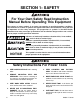
SECTION 1: SAFETY For Your Own Safety Read Instruction Manual Before Operating This Equipment The purpose of safety symbols is to attract your attention to possible hazardous conditions. This manual uses a series of symbols and signal words which are intended to convey the level of importance of the safety messages. The progression of symbols is described below. Remember that safety messages by themselves do not eliminate danger and are not a substitute for proper accident prevention measures.
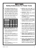
Safety Instructions For Power Tools 9. USE PROPER EXTENSION CORD. Make sure your extension cord is in good condition. Conductor size should be in accordance with the chart below. The amperage rating should be listed on the motor or tool nameplate. An undersized cord will cause a drop in line voltage resulting in loss of power and overheating. Your extension cord must also contain a ground wire and plug pin. Always repair or replace extension cords if they become damaged.
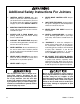
Additional Safety Instructions For Jointers 1. 2. JOINTING SAFETY BEGINS with your lumber. Inspect your stock carefully before you feed it over the cutterhead. If you have any doubts about the stability or structural integrity of your stock, DO NOT JOINT IT! MAINTAIN PROPER RELATIONSHIPS of infeed and outfeed table surfaces and cutterhead knife path. 3. ALWAYS USE A PUSH BLOCK when jointing. Never place your hands directly over the cutterhead. 4.
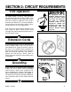
SECTION 2: CIRCUIT REQUIREMENTS 110V Operation The Model H2801 is wired for 110V operation. The motor will safely draw 5 amps at 110V. If you operate this machine on any circuit that is already close to its capacity, it might blow a fuse or trip a circuit breaker. However, if an unusual load does not exist and the circuit still trips, contact a qualified electrician or our service department. A 10 amp fuse or circuit breaker should be used when fusing this jointer.
SECTION 3: GENERAL INFORMATION Commentary Grizzly Industrial, Inc. is proud to offer the Model H2801 4" Jointer. This jointer is part of Grizzly’s growing family of fine woodworking and metalworking machinery. When used according to the guidelines stated in this manual, you can expect years of trouble-free, enjoyable operation. The Model H2801 offers a 1⁄2 H.P., 110V, 8000 R.P.M. motor, a 2 knife cutterhead, and a 45˚ tilting fence. We are also pleased to provide this manual with the Model H2801.
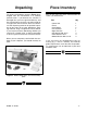
Unpacking Piece Inventory The jointer and hardware (shown in Figure 2) are shipped from the manufacturer in a carefully packed carton. If you discover the machine is damaged after you have signed for delivery, and the truck and driver are gone, you will need to file a freight claim with the carrier. Save the containers and all packing materials for possible inspection by the carrier or its agent. Without the packing materials, filing a freight claim can be difficult.
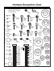
Hardware Recognition Chart WASH 5/8 10/24 WASH Button Head Screw Flange Bolt 3 WASH S WA H ASH 1/4 D ER I ASHE ASH 8mm 6mm DI ER ASH ASHE WASH DIA ER S WA H LINES ARE 1MM APART WASHERS ARE MEASURED BY THE INSIDE DIAMETER 2-3/4 R DIA ET AM 2-1/2 5/16 ET AM 2-1/4 R DIA MET 2 METE 1-3/4 3/8 4mm 10mm TE ME R 16mm 1-1/2 D ER IA MET 12mm 10/24 5/16 7/16 9/16 3/4 7/8 1 1-1/4 DI ER ET AM 10mm 1/4 3/8 1/2 5/8 D ER IA ETER M 8mm 5mm 10mm 15mm 20mm 25mm 30mm 35mm 40mm
Clean Up The unpainted surfaces may be coated with a waxy oil to protect them from corrosion during shipment. Remove this protective coating with a solvent cleaner or citrus-based degreaser such as Grizzly’s G7895 Degreaser. To clean thoroughly, some parts may need to be removed. Avoid chlorine-based solvents as they may damage painted surfaces should they come in contact. Always follow the manufacturer’s instructions when using any type of cleaning product.
SECTION 4: ASSEMBLY Beginning Assembly Trunnions Most of your Model H2801 4" Jointer has been assembled at the factory, but some parts must be assembled or installed after delivery. We have organized the assembly process into steps. Please follow along in the order presented in this section. The plunger trunnion and the scale trunnion need to be attached to the rear of the fence. To attach the trunnions: Keep loose clothing out of the way of machinery and keep hair pulled back. 1.
Fence To attach the fence to the jointer table: 1. Mount the fence assembly as shown in Figure 4 with the four M5-.8 x 10 cap screws and lock washers. 2. Verify that the fence is secure. Figure 4. Attaching fence to jointer. Mounting Jointer The Model H2801 weighs approximately 22 lbs. Make sure that the workbench on which you plan to mount the jointer is sturdy enough to hold the combined weight of the machine and the wood stock being processed.
SECTION 5: ADJUSTMENTS Keep loose clothing out of the way of machinery and keep hair pulled back. Disconnect power to the machine when performing any adjustments or maintenance. Failure to do this may result in serious personal injury. Figure 6. Straightedge across outfeed table. Wear safety glasses during the entire adjustment process. Failure to comply may result in serious personal injury.
Fence The fence on the Model H2801 can be adjusted to cut various angles from -45˚ to 45˚. The fence can be tilted -45˚ toward the cutterhead for better stability with narrow workpieces, or the fence can be tilted to 45˚ away from the cutterhead for cutting large angles. To adjust the fence angle: 1. Loosen the lock knobs on both sides of the fence. 2. The angle gauge shown in Figure 8 is behind the left end of the fence. 3.
Knife Adjustment To ensure accurate cutting, the knives must be .003" higher than the outfeed table at the highest point. To check or adjust the knife height: Figure 10. Cutterhead guard. 1. Unplug the power from the machine! 2. Block the cutterhead guard from closing with a scrap piece of wood between the fence and the cutterhead guard, or remove the cutterhead guard. 3. Rotate the cutterhead so that one of the knives is at the highest position. 4.
SECTION 6: OPERATIONS Keep loose clothing out of the way of machinery and keep hair pulled back. Disconnect power to the machine when performing any adjustments or maintenance. Failure to do this may result in serious personal injury. Wear safety glasses during all operations on the jointer. Failure to comply may result in serious personal injury. Always wear a dust mask when operating the jointer. Using this machine produces sawdust which may cause allergic reactions or respiratory problems.
Lock-Out Switch To ensure the safety of your work place, a lock out switch has been provided with the Model H2801. To use the lock-out feature, simply pull the lock-out key when the switch is in the OFF position, as shown in Figure 12. When jointing, always cut with the grain rather than against it. Cutting against the grain (going against the pattern of the wood growth rings) chips the wood instead of cutting it, making the workpiece rough and irregular.
Push Blocks To feed the workpiece: 1. 2. 3. 4. Hold the board firmly down on the infeed table and against the fence. Use push blocks if you are surface planing or your situation requires it. Feed the board toward/over the cutterhead at a consistent and even rate of speed. Do not force the board into the cut. Also, any hesitation or stopping could cause uneven cuts or cutting inconsistencies on your workpiece. Use a hand-over-hand action to “walk” the workpiece over the cutterhead.
Dust Collection Surface Planing Any standard dust collection hose can be attached to the 21⁄2" dust dust port (Figure 15) on the back of the Model H2801. To attach a dust collecting system: The purpose of planing on a jointer is to produce one flat surface. Once you have one flat surface on a board, it can then more readily be milled to precise, final dimensions on a thickness planer.
Edge Joining Beveling The purpose of edge joining is to produce a finished, flat-edged surface that is suitable for joinery or finishing. Edge joining is also a necessary step prior to ripping stock to width on a table saw or radial arm saw. Beveling an edge is essentially the same operation as edge joining, except that the fence is tilted to a specified angle. Use extra care to ensure that the edge makes solid contact with the infeed and outfeed tables at all times. 1.
SECTION 7: MAINTENANCE Lubrication Disconnect power to the machine when performing any adjustments or maintenance. Failure to do this may result in serious personal injury. General Since all bearings are sealed and permanently lubricated, simply leave them alone until they need to be replaced. Do not lubricate them. Table ways and the fence assembly should not be lubricated. If the tables appear to be stuck, disassemble and clean any foreign materials from the ways.
Replacing Knives To replace the cutterhead knives: 1. Unplug the power from the jointer! 2. Block the cutterhead guard so it stays open, or remove the cutterhead guard. Lift the knife and knife clamp from the cutterhead and clean any sawdust and resin buildup from the cutterhead and knife clamp. 3. Position the knife clamp against the replacement knife and install the assembly in the cutterhead. 4. Secure the knife and knife clamp with the three knife clamp screws.
SECTION 8: CLOSURE The following pages contain general machine data, parts diagrams/lists, troubleshooting guide and Warranty/Return information for your Model H2801 4" Jointer. If you need parts or help in assembling your machine, or if you need operational information, we encourage you to call our Service Department. Our trained service technicians will be glad to help you.
MACHINE DATA SHEET Customer Service #: (570) 546-9663 • To Order Call: (800) 523-4777 • Fax #: (800) 438-5901 GRIZZLY MODEL H2801 4" JOINTER Design Type ....................................................................................................Bench Model Capacities: Maximum Depth of Cut ............................................................................................5⁄64" Maximum Width of Cut ..............................................................................................
-24- H2801 4" Jointer
REF 01 02 03 04 05 06 07 08 09 10 11 12 13 14 15 16 17 18 19 20 21 22 23 24 25 26 27 28 29 30 31 32 33 34 35 36 37 38 39 40 PART # PH2801001 PH2801002 PH2801003 PH2801004 PH2801005 PH2801006 PH2801007 PH2801008 PH2801009 PH2801010 PH2801011 PH2801012 PH2801013 PH2801014 PH2801015 PH2801016 PH2801017 PH2801018 PH2801019 PH2801020 PH2801021 PH2801022 PH2801023 PH2801024 PH2801025 PH2801026 PH2801027 PH2801028 PH2801029 PH2801030 PH2801031 PH2801032 PH2801033 PH2801034 PH2801035 PH2801036 PH2801037 PH280103
WARRANTY AND RETURNS Grizzly Industrial, Inc. warrants every product it sells for a period of 1 year to the original purchaser from the date of purchase. This warranty does not apply to defects due directly or indirectly to misuse, abuse, negligence, accidents, repairs or alterations or lack of maintenance.
WARRANTY CARD Name ____________________________________________________________________________________ Street ____________________________________________________________________________________ City ______________________________________________________________State________Zip_________ Phone Number_______________________E-Mail_______________________FAX________________________ MODEL # H2801 4" Jointer Order #______________________________________________ The following information is given on a voluntary ba
FOLD ALONG DOTTED LINE Place Stamp Here GRIZZLY INDUSTRIAL, INC. P.O.