3 HP AIR COMPRESSOR MODEL H3372 INSTRUCTION MANUAL COPYRIGHT © APRIL, 2003 BY GRIZZLY INDUSTRIAL, INC. WARNING: NO PORTION OF THIS MANUAL MAY BE REPRODUCED IN ANY SHAPE OR FORM WITHOUT THE WRITTEN APPROVAL OF GRIZZLY INDUSTRIAL, INC. PRINTED IN CHINA ONLINE MANUAL DISCLAIMER THE INFORMATION IN THIS MANUAL REPRESENTS THE CONFIGURATION OF THE MACHINE AS IT IS CURRENTLY BEING SHIPPED. THE MACHINE CONFIGURATION CAN CHANGE AS PRODUCT IMPROVEMENTS ARE INCORPORATED.
WARNING Some dust created by power sanding, sawing, grinding, drilling, and other construction activities contains chemicals known to the State of California to cause cancer, birth defects or other reproductive harm. Some examples of these chemicals are: • Lead from lead-based paints. • Crystalline silica from bricks, cement, and other masonry products. • Arsenic and chromium from chemically treated lumber. Your risk from these exposures varies, depending on how often you do this type of work.
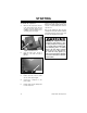
SAFETY For Your Own Safety Read Instruction Manual Before Operating This Equipment The purpose of safety symbols is to attract your attention to possible hazardous conditions. This manual uses a series of symbols and signal words which are intended to convey the level of importance of the safety messages. The progression of symbols is described below. Remember that safety messages by themselves do not eliminate danger and are not a substitute for proper accident prevention measures.
Safety Instructions For Pneumatic Tools 10. USE PROPER AIR HOSE for the tool. Make sure your air hose is in good condition and is long enough to reach your work without stretching. 11. WEAR PROPER APPAREL. DO NOT wear loose clothing, gloves, neckties, rings, bracelets, or other jewelry which may get caught in moving parts. Non-slip footwear is recommended. Wear a protective hair covering to contain long hair. 12. ALWAYS USE SAFETY GLASSES. Also use a face or dust mask if cutting operation is dusty.
Additional Safety For Air Compressors 1. 2. 3. 4. 5. 6. READ THIS ENTIRE MANUAL BEFORE OPERATING THE COMPRESSOR. OPERATE THE COMPRESSOR IN A WELL VENTILATED AREA free of acids, vapor, explosive gases and flammable or unstable materials. DO NOT PULL ON THE GAUGES OR REGULATORS TO MOVE THE COMPRESSOR! DO NOT USE THE COMPRESSOR FOR FILLING BREATHING OR DIVING APPARATUS. Compressed air from this compressor cannot be used for pharmaceutical, food or health requirements without further treatment.
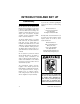
INTRODUCTION AND SET UP Commentary We are proud to offer the Grizzly Model H3372 3 HP Air Compressor. This model is part of a growing Grizzly family of fine power tools. When used according to the guidelines set forth in this manual, you can expect years of trouble-free, enjoyable operation and proof of Grizzly’s commitment to customer satisfaction. The Model H3372 features a powerful 220V 3 HP motor, two cylinder aluminum pump with cast iron cylinder liners, an incredible 10.9 CFM@ 40 PSI, 9.
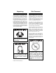
Unpacking Site Placement This air compressor is shipped from the manufacturer in a carefully packed carton. If you discover the machine is damaged after you have signed for delivery, and the truck and driver are gone, you will need to file a freight claim with the carrier. Save the containers and all packing materials for possible inspection by the carrier or its agent. Without the packing materials, filing a freight claim can be difficult.
CIRCUIT REQUIREMENTS 220V Operation Grounding Wiring: The Model H3372 3 HP Air Compressor is wired for 220V operation. In the event of an electrical short, grounding reduces the risk of electric shock by providing a path of least resistance to disperse electric current. These machines are equipped with power cords having an equipment-grounding conductor. See Figure 1. The outlet must be properly installed and grounded in accordance with all local codes and ordinances.
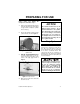
PREPARING FOR USE Before using your Grizzly Compressor, follow these steps : 1. 2. Air Remove all packing materials and any protective plastic bags, zip-tie labels or tags from the compressor cylinder head or oil plug. Be sure the air filter is attached to the cylinder head as shown in Figure 2. NOTICE The machine should never be run without a full oil reservoir. The oil provides lubrication to the cylinder rings which deliver the compressed air.
STARTING To start the air compressor: 1. Make sure the compressor switch is in the OFF position (knob with red cap above pressure gauges shown in Figure 4 pressed down) before connecting the power supply. Figure 4. ON/OFF button. 2. Close the drain valve, shown in Figure 5, so the tank can build up pressure. Check the pressure gauge to see that the tank pressure climbs to approximately 100115 PSI or around 8 BAR, then automatically turns off.
AIR CONTROL Delivered Pressure Air Release The tank pressure is displayed on the left pressure gauge, and the air to be delivered to the tool is displayed on the right pressure gauge shown in Figure 6. There are two ways to release air from the compressor tank other than through your regulator and the use of air tools: —The drain valve. —The safety drain valve. To release air by using the drain valve, simply turn the release nut to allow air to flow out of the tank. The drain valve is shown in Figure 5.
Tank Pressure Regulator The pressure regulator has been factory set for the highest quality operating performance. The pressure regulator adjusts the desired PSI range where the air compressor kicks in and out to keep the tank pressurized for the best operating performance. To adjust the pressure regulator: 1. Unplug the air compressor from the power supply. 2. Make sure the compressor switch is in the OFF position. 3. Drain the pressure from the tank. 4.
CONNECTING TOOLS To connect air tools to your air compressor: 1. Make sure the compressor model you use has a sufficient cubic feet per minute (CFM) output for the air tool you plan to connect. (Most air tools will have an air requirement stated in terms of a specific CFM at a specific pressure.) 2. The compressor should put out a higher CFM than the tool requires. Consideration should also be given to the type of usage.
MAINTENANCE Before Each Use Regular periodic maintenance on your Air Compressor will ensure its optimum performance. Make a habit of inspecting the following items before each time you use the air compressor. Check the following items: 1. Check Oil Level! Use the sight gauge on the bottom of the crankcase to make sure the oil level is at the proper height. 2. Drain the tanks of any condensation by opening the drain valve on the bottom of the tank.
Changing V-belt To change the V-belt drive on your air compressor: 1. Remove the belt guard from the air compressor shown in Figure 11. The guard is attached to the compressor frame by the two mounting bolts shown in Figure 11. 3. Remove the V-belt from the motor pulley and fly pulley. 4. Install the new V-belt. 5. Reposition the motor in its original place so the belt is tensioned, and secure the four mounting bolts loosened in step 2. 6.
After First 50 Hours Of Use After the first 50 working hours or 30 days, whichever comes first, perform the following maintenance: • Replace the oil in the motor with compressor oil (use ISO 100 of SAE 30W viscosity, non detergent type). • Make sure that all the fittings are tight. • Remove the air filter foam element shown in Figure 14 and rinse it out with water. Allow it to dry and reinstall.
Every 300 Hours Storage After every 300 hours or 3 months of regular operation, perform the following maintenance items: When storing your air compressor follow these guidelines: • Change the compressor motor oil. Use compressor oil or a non-detergent 30 weight oil. • Rinse the air filter foam element in water. • Check for air leaks and correct as needed. • Clean the cylinder head fins for proper cooling. • 1. Set the ON/OFF button to OFF. 2.
TROUBLESHOOTING PROBLEM CAUSE ACTION Pump motor will not start. 1. Low voltage. 2. Open circuit in motor, switch or cord. 3. Tank already pressurized. 4. Thermal overload switch. 1. Check power line for proper voltage. 2. Inspect all lead connections on motor, switch and cord for loose or open connections. 3. Motor will not start if tank pressure is too high. 4. Thermal overload switch has tripped, wait for motor to cool, then reset switch by pressing red button.
PROBLEM CAUSE ACTION Motor runs hot. 1. Cooling fins dirty. 2. Air filter clogged. 3. Compressor is exceeding its dutycycle. 1. Clean cylinder fins and motor area. 2. Inspect and clean air filter. 3. Do not allow the compressor to run over its recommended duty cycle. Pressure relief valve stays open and motor won’t stop running. 1. Faulty pressure switch, unit is trying to overpressure the tank. 2. Faulty pressure relief valve. 1. Turn compressor off, unplug from power supply, drain tank.
Model H3372 3 HP Air Compressor 36 47 35 37 48 18 38 49 19 34 20 51 50 23 33 76 94 22 29 27 21 32 77 3 31 90 78 5 30 4 29 28 93 80 7 6 26 25 1 2 79 11 24 44 10 43 39 9 69 68 40 9 42 8 41 67 14 61 65 91 15 63 92 63 66 12 13 65 16 64 66 52 17 65 64 59 60 63 64 57 55 54 58 81 56 53 71 46 45 73 89 74 75 72 65 70 82 63 84 62 63 88 83 87 85 86 95 96 -18- H3372 3 HP Air Compressor
REF 1 2 3 4 5 6 7 8 9 10 11 12 13 14 15 16 17 18 19 20 21 22 23 24 25 26 27 28 29 30 31 32 33 34 35 36 37 38 39 PART # PH3372001 P6202 PH3372003 PH3372004 PSB29M PLW03M PN01M PH3372008 PH3372009 PH3372010 PH3372011 PH3372012 PW01M PB09M PH3372015 PH3370024 PH3372017 PH3372018 PH3372019 PH3372020 PH3372021 PH3370017 PR49M PH3372024 PH3372025 PH3372026 PH3372027 PB108M PLW09M PH3372030 PH3372031 PH3372032 PB109M PH3372034 PH3372035 PSB98M PH3372037 PH3372038 PH3372039 H3372 3 HP Air Compressor DESCRIPTION
REF 40 41 42 43 44 45 46 47 48 49 50 51 52 53 54 55 56 57 58 59 60 61 62 63 64 65 66 67 68 69 70 71 72 73 74 75 76 77 78 -20- PART # PH3372040 PH3372041 PH3372042 PLW04M PB20M PH3372045 PH3372046 PH3372047 PH3372048 PH3372049 PH3370062 PH3372051 PH3372052 PH3372053 PH3370057 PH3370058 PH3372056 PH3372057 PH3372058 PH3372059 PH3372060 PH3372061 PH3372062 PW01M PLW04M PN03M PB26M PH3372067 PH3372068 PK41M PH3372070 PH3372071 PB08M PW03M PLW03M PN01M PH3372076 PH3372077 PH3372078 DESCRIPTION O-RING PULLEY GA
REF 79 80 81 82 83 84 85 86 87 88 89 90 91 92 93 94 95 96 PART # PH3372079 PH3372080 PB21M PH3370070 PB09M PH3372084 PB80M PH3372086 PW08M PN13M PH3372089 PH3372090 PH3372091 PH3372092 PH3372093 PH3372094 PH3372095 PH3372096 H3372 3 HP Air Compressor DESCRIPTION BELT A1143 HANDLE HEX BOLT M8-1.25 X 42 DRAIN VALVE 14MM HEX BOLT M8-1.25 X 20 CUSHION FOOT HEX BOLT M16-2.0 X 55 PNEUMATIC TIRE 8.5" FLAT WASHER 16MM HEX NUT M16-2.
WARRANTY AND RETURNS Grizzly Industrial, Inc. warrants every product it sells for a period of 1 year to the original purchaser from the date of purchase. This warranty does not apply to defects due directly or indirectly to misuse, abuse, negligence, accidents, repairs or alterations or lack of maintenance.
WARRANTY CARD Name __________________________________________________________ Street __________________________________________________________ City____________________State________Zip_________ Phone Number____________E-Mail___________________FAX____________ Model #_______________Serial#________________Order #______________ The following information is given on a voluntary basis. It will be used for marketing purposes to help us develop better products and services.
Send a Grizzly Catalog to a friend: Name________________________________ Street________________________________ City______________State______Zip_______ FOLD ALONG DOTTED LINE Place Stamp Here GRIZZLY INDUSTRIAL, INC. P.O.