MODEL H6329 21⁄2 GALLON PAINT TANK INSTRUCTION MANUAL Copyright © MAY, 2009 By Grizzly Industrial, Inc. Warning: No portion of this manual may be reproduced in any shape or form without the written approval of Grizzly Industrial, inc.
This manual provides critical safety instructions on the proper setup, operation, maintenance and service of this machine/equipment. Failure to read, understand and follow the instructions given in this manual may result in serious personal injury, including amputation, electrocution or death. The owner of this machine/equipment is solely responsible for its safe use.
SAFETY For Your Own Safety Read Instruction Manual Before Operating This Equipment The purpose of safety symbols is to attract your attention to possible hazardous conditions. This manual uses a series of symbols and signal words which are intended to convey the level of importance of the safety messages. The progression of symbols is described below. Remember that safety messages by themselves do not eliminate danger and are not a substitute for proper accident prevention measures.
Safety Instructions for Pneumatic Tools 7. AVOID ENTANGLEMENTS. Do not wear loose clothing, gloves, neckties, rings, bracelets, or other jewelry, which may get caught in moving parts, when operating this tool. Wear a protective hair covering to contain long hair. 8. USE CORRECT AIR PRESSURE. Exceeding the maximum PSI rating of this tool may cause unpredictable operation or bursting. 9. DISCONNECT AIR PRESSURE before servicing, changing accessories, or moving to another location.
Additional Safety Instructions for Paint Tanks 1. Read this manual. This manual contains proper operating instructions for using this paint tank. 2. DESIGN MODIFICATIONS. Do not modify the tank design or construction. Drilling into the tank or welding on attachments, or altering its design, will weaken the tank. 3. CLEANING AND MAINTENANCE. Clean and dry the tank and lid according to the instructions in this manual.
INTRODUCTION Foreword The specifications, details, and photographs in this manual represent the Model H6329 as supplied when the manual was prepared. However, owing to Grizzly’s policy of continuous improvement, changes may be made at any time with no obligation on the part of Grizzly. Specifications Paint Tank Material Capacity ...........21/2 Gallons (10 L) Operating Pressure ...................10–45 PSI Maximum Operating Pressure...........45 PSI Tank Construction........
SETUP Unpacking Inventory Your paint tank was carefully packaged for safe shipping. If you discover any damage after you have signed for delivery, immediately call Customer Service at (570) 5469663 for advice. H6329 Inventory (Figure 1)................ Qty A. Paint Tank............................................ 1 B. Caster Wheel Assemblies.................... 4 —Hex Nuts M8-1.25................................. 4 —Flat Washers 8MM................................ 4 —Lock Washers 8MM.....................
Tank Assembly Mixing Handle and Crank Carrying Handle Tank Pressure Regulator Pressure Relief Valve Vent Valve Tank Pressure Gauge Figure 2. Controls and features. To assemble the paint tank: 1. Open the lid and remove the hardware shipped with the tank. 5. Connect the 1/4" push-on hose fittings to your air supply hose and onto the inlet fitting on the regulator (Figure 4). 2. Install the four caster assemblies with the hex nuts and washers, as shown in Figure 3. Figure 4.
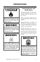
OPERATIONS Tank Regulator and Spray Guns The pressure regulator on the paint tank controls the pressure in the tank. In turn, the paint is fed to the spray gun at this tank pressure. EXPLOSION HAZARD! DO NOT smoke or have any source of flame or spark near spraying. Vapors will explode if ignited. Do not exceed the 45 PSI maximum operating pressure on your paint tank. Exceeding the maximum pressure may cause the tank to explode, causing serious personal injury.
Operation EXPLOSION HAZARD! Never exceed 45 PSI when pressurizing the tank. To use the paint tank: 1. Open the vent valve (Figure 6) to exhaust any tank pressure, and observe the tank regulator gauge (Figure 5) to make sure the tank un-pressurized. 2. Open the lid. Mix and strain your paint into the tank. 3. Wipe a thin layer of petroleum jelly onto the rubber lid seal, and secure the lid to the tank by tightening the four wing nuts in an alternating pattern. Read the manual before operation.
CLEANING AND LUBRICATION Cleaning the Tank Proper cleaning is the best way to ensure trouble free performance from your paint tank. If your tank is not thoroughly cleaned, damage and poor operation will result. Problems caused by improper cleaning will not be covered by the warranty. Clean the tank immediately after each use. To clean the paint tank: 1.
Tank Troubleshooting Symptom Possible Cause Solution Air escaping from regulator port. 1. Broken or damaged diaphragm in tank regulator. 1. Replace tank regulator. Pressure dropping slowly on regulator. 1. Dirty or worn valve seat in regulator. 2. Loose air fittings leaking air. 1. Replace tank regulator. 1. Defective lid gasket. 2. Wing screw loose. 1. Replace lid gasket. 2. Tighten wing screws evenly. 3. Clean rim and gasket. Fluid or air leak at lid gasket. 3.
Troubleshooting Symptom Possible Cause Solution Fluttering or spitting spray. 1. Dry or worn fluid tip seat permits air to seep into fluid passage. 1. Tighten fluid tip or replace seat with new one. 2. Material level too low. 2. Add material. 3. Fluid tip or filter obstructed. 3. Clean. 4. Dry needle packing. 4. Lubricate needle. 1. Atomizing cap holes are obstructed. 1. Clear holes. 2. Build-up material on top or bottom of fluid tip. 2. Clean. 3.
Symptom Possible Cause Solution Excessive overspray. 1. Fluid pressure too high. 2. Gun is too far from surface. 1. Reduce fluid pressure. 2. Keep gun at recommended distance. 3. Slow down and maintain consistent, even parallel stroke. 3. Spraying too fast. Unable to control spray fan. 1. Pattern adjustment screw is not seating properly. 2. Atomizing cap is loose. 1. Clean or replace. Runs and sags. 1. Over diluted paint. 1. Refer to paint manufacture dilution ratios. 2.
H6329 PAINT TANK 29 28 21 32 30 31 33 5 27 34 5 26 35 25 36 24 1 3 39 38 2 38 4 20 5,6,37 7 8 9 10 11 16 19 13 12 14 15 17 18 17-1 22,23 21 17-2 REF PART # DESCRIPTION REF PART # DESCRIPTION 1 2 3 4 5 6 7 8 9 10 11 12 13 14 15 16 17 17-1 17-2 18 19 HANDLE LID GASKET COMPLETE LID ASSEMBLY TANK HEX NUT M8-1.