MODEL H8154 AC/DC STICK/TIG WELDER OWNER'S MANUAL COPYRIGHT © MAY, 2007 BY GRIZZLY INDUSTRIAL, INC. WARNING: NO PORTION OF THIS MANUAL MAY BE REPRODUCED IN ANY SHAPE OR FORM WITHOUT THE WRITTEN APPROVAL OF GRIZZLY INDUSTRIAL, INC.
����������������������������������������������������������������������� �������������������������������������������������������������� ���������������������������������������������������������������������� �������������������������������������������������������������������� ������������������������ ������������������������������������������������������������������ �������������������������������������������������������������������� ����������������������������������������������������������������� ����������
Table of Contents INTRODUCTION ............................................................................................................................... 2 Foreword .................................................................................................................................... 2 Contact Info ................................................................................................................................ 2 Specifications ................................................
INTRODUCTION Foreword Contact Info We are proud to offer the Model H8154 AC/DC Stick/TIG Welder. This machine is part of a growing Grizzly family of fine metalworking equipment. When used according to the guidelines set forth in this manual, you can expect years of trouble-free, enjoyable operation and proof of Grizzly’s commitment to customer satisfaction.
Specifications Stick Welding Current..............................5–130A Stick Duty Cycle .............................35% @ 130A AC TIG Welding Current .......................20–160A AC TIG Duty Cycle .........................35% @ 160A AC TIG Square Wave Balance .............. 30–70% AC TIG Square Wave Frequency ........20-100Hz DC TIG Welding Current .........................5–160A DC TIG Duty Cycle .........................35% @ 160A DC TIG Current Upslope .........................0.2 sec.
����������������� �������������������������������������� ������������������������������������ �������������������������������������������������������������������������������������������������� �������������������������������������������������������������������������������������������� �������������������������������������������������������������������������������������������� �������������������������������������������������������������������������������������������� �������������������� �������������������
4. ELECTRIC SHOCK. DO NOT touch live electrical parts. Connect welder to power source with approved earth ground. Make sure all electrical connections are tight, clean, and dry. Connect workpiece to approved earth ground. The work lead is NOT a ground connection and is to be used only to complete the working welding circuit. 5. PREVENT FIRES.
Additional Sources Additional Sources for Welding Codes and Standards American Welding Society, 550 N.W. LeJeune Road, Miami, FL 33126, (305) 443-9353, Website: www. aws.org. —Safety in welding, Cutting, and Allied Processes, ANSI Standard Z49.1 —Recommended Safe Practices for the Preparation for Welding and Cutting of Containers and Piping, AWS F4.1 National Fire Protection Association, P. O. Box 9101, 1 Battery March Park, Quincy, MA 02269-9101, (617) 770-3000, Website: www.nfpa.org and www.sparky.org.
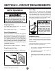
Circuit Requirements SECTION 2: CIRCUIT REQUIREMENTS 220V Operation Serious personal injury could occur if you connect the machine to the power source before you have completed the set up process. DO NOT connect the machine to the power source until instructed to do so. Grounding In the event of an electrical short, grounding reduces the risk of electric shock.
Grounding for Welding Safety There are two or more electrical circuits involved in any welding operation. The practice of safely grounding these circuits is documented in various codes and standards (refer to Additional Sources for Welding Codes and Standards on Page 6). Welding Machine Ground When properly connected to a power source, the Model H8154 welder is grounded through the power cord and local power grid. The internal welding circuit of the welder is insulated from the external enclosure.
SECTION 3: INVENTORY The Model H8154 was carefully packed when it left our warehouse. If you discover the machine is damaged or a part is missing after you have signed for delivery, please immediately call Customer Service at (570) 546-9663 for advice. Save the containers and all packing materials for possible inspection by the carrier or its agent. Otherwise, filing a freight claim can be difficult. When you are completely satisfied with the condition of your shipment, inventory the contents.
SECTION 4: OPERATIONS Operation Safety Damage to your eyes and lungs could result from using this machine without proper protective gear. Always wear safety glasses, welder's helmet, and a respirator when operating this welder. NOTICE If you have never used this type of machine or equipment before, WE STRONGLY RECOMMEND that you read books, trade magazines, or get formal training before beginning any projects.
Welder Controls D A B NOTICE After completing the welding operation, keep the power to the welder ON for a period of time to let the welder fan cool the welder down. To avoid damage to your welder, never shut the power OFF before the welder enclosure is completely cool to the touch. E C F E. Warning Light: —Not Lit: The welder is ready for use. Figure 7. Model H8154 controls.
I. 4. Release the torch thumb switch at any time to raise the welding current to the selected output current over the preset upslope time of 0.2 seconds. 2-Step/4-Step Selector (TIG only): Select either the 2-step or 4-step sequence for TIG welding. Note: The foot remote control can be substituted for the torch thumb switch in these steps. 5. Press the thumb switch again to end the welding operation. —2-Step 6.
General Welding Operations 6. Decide which type of weld is correct for your project and properly prepare the metal. 7. Select the correct settings on the front control panel for your welding operation. Becoming a good welder takes a lot of practice and experience. If you are a novice, read books and get help from an experienced welder before beginning a welding operation. 8. Make sure all connections, hoses, gas cylinder, and grounds are correct and secure.
ACCESSORIES SECTION 5: ACCESSORIES H7786—Auto Darkening Welding Helmet Automatic UV and IR filters protect eyes from harmful visible and invisible light during welding. Switching time is less than or equal to 2 milliseconds, so there's no need to flip the helmet up to see your work under normal light conditions. Full face protection features adjustable head suspension and adjustable delay time, sensitivity and dark shade protection. Viewing area is 31⁄ 2" x 11⁄ 2". Includes 2 AAA batteries. Figure 8.
Troubleshooting SECTION 6: SERVICE Review the troubleshooting and procedures in this section to fix or adjust your machine if a problem develops. If you need replacement parts or you are unsure of your repair skills, then feel free to call our Technical Support at (570) 546-9663. Troubleshooting Symptom Possible Cause Possible Solution Welder does not 1. Plug/receptacle is at fault or wired incor- 1. Test for good contacts; correct the wiring. power up or the rectly. breaker trips. 2.
Symptom Possible Cause Failure of weld to 1. Insufficient heat applied to weld. fuse completely with 2. Improper welding technique. base metal or prior weld bead. 3. Workpiece dirty. 4. Duty cycle exceeded. Unstable arc. 1. Weld circuit polarity is incorrect. 2. Tungsten rod is contaminated (TIG). 3. Arc too long. 4. Workpiece is dirty or damp. 5. Incorrect gas or gas settings (TIG). Arc wanders. 1. Improper gas flow (TIG). 2. Arc too long. 3. Contaminated electrode/tungsten rod. 4.
Replacement Parts & Labels 12 13 17 18 3 1 4 5 15 2 6 11 7 8 9 16 14 10 REF PART # DESCRIPTION REF PART # DESCRIPTION 1 2 3 4 5 6 7 8 9 GAS INLET TUBE COLLET BODY GAS NOZZLE #4 GAS NOZZLE #5 GAS NOZZLE #6 LONG COLLET BACKCAP SMALL COLLET BACKCAP COLLET 1.6MM COLLET 1.
������������� ���������������������������������������������������������������������������������� � ������������������������������������������������������������������������������������ ����� ����������������������� ������������������������������� ���� ��������������������� ���������������������������� ������ ������������������������ ��������������������������� ���������������������������� ������������������������������� ��������������������������� �������������������������������������������������������������
���������������������� ����� ����� ���� ������������������������ ������������� �������������������������� ���������������������� ����������������������������������� ����������������������������������� ������������������������������������� �������������������������������������� ��������������������������������������
WARRANTY AND RETURNS Grizzly Industrial, Inc. warrants every product it sells for a period of 1 year to the original purchaser from the date of purchase. This warranty does not apply to defects due directly or indirectly to misuse, abuse, negligence, accidents, repairs or alterations or lack of maintenance.
����������������������������������������������������������������������� ������������������������������������� ������������������������������������ ����������������� �������������������������������� ��������������������������������� ���� ��������������������� ������������������