MODEL H8232 3-PIECE FRAMING/FINISH/PALM NAILER KIT OWNER'S MANUAL COPYRIGHT © SEPTEMBER, 2007 BY GRIZZLY INDUSTRIAL, INC. WARNING: NO PORTION OF THIS MANUAL MAY BE REPRODUCED IN ANY SHAPE OR FORM WITHOUT THE WRITTEN APPROVAL OF GRIZZLY INDUSTRIAL, INC.
����������������������������������������������������������������������� �������������������������������������������������������������� ���������������������������������������������������������������������� �������������������������������������������������������������������� ������������������������ ������������������������������������������������������������������ �������������������������������������������������������������������� ����������������������������������������������������������������� ����������
SAFETY For Your Own Safety Read Instruction Manual Before Operating This Equipment The purpose of safety symbols is to attract your attention to possible hazardous conditions. This manual uses a series of symbols and signal words which are intended to convey the level of importance of the safety messages. The progression of symbols is described below. Remember that safety messages by themselves do not eliminate danger and are not a substitute for proper accident prevention measures.
Safety Instructions for Pneumatic Tools 10. USE PROPER AIR HOSE for the tool. Make sure your air hose is in good condition and is long enough to reach your work without stretching. 17. DISCONNECT TOOLS before servicing, changing accessories, or moving to another location. 11. WEAR PROPER APPAREL. Do not wear loose clothing, gloves, neckties, rings, bracelets, or other jewelry which may get caught in moving parts. Non-slip footwear is recommended. Wear a protective hair covering to contain long hair. 19.
Additional Safety Instructions for Nailers 1. HAND INJURIES: Do not place your hands near the nail point of entry. A nail can deflect and tear through the surface of the workpiece, puncturing your hand or fingers. 2. COMBUSTIBLE GASES: Never connect the nailer to pressurized oxygen or other combustible gases as an air source. Only use filtered, lubricated, and regulated compressed air. 3.
Never point these nailers at yourself or another person! Always pay attention to the direction these nailers are pointed. Use these tools with respect and caution to lessen the possibility of operator or bystander injury. Ignoring this warning may result in serious personal injury. Read the manual before operation. Become familiar with these nailers, their safety instructions, and their operation before beginning any work.
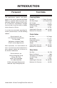
INTRODUCTION Foreword The specifications, details, and photographs in this manual represent the Model H8232 as supplied when the manual was prepared. However, owing to Grizzly’s policy of continuous improvement, changes may be made at any time with no obligation on the part of Grizzly. If you have any comments regarding this manual, please write to us at the following address: Grizzly Industrial, Inc. C/O Technical Documentation P.O. Box 2069 Bellingham, WA 98227-2069 E-Mail: manuals@grizzly.
SET UP Unpacking Inventory Your new nailer kit was carefully packaged for safe shipping. If you discover any damage after you have signed for delivery, immediately call Customer Service at (570) 546-9663 for advice. After you open the nailer case, you should find the following. Save the containers and all packing materials for possible inspection by the carrier or its agent. Otherwise, filing a freight claim can be difficult.
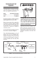
Compressed Air System The Model H8232 is designed to be operated at the following air pressures using clean, dry, regulated, compressed air: Nailer Operating Air Pressure Framing ................................... 80–110 PSI Finish ....................................... 60–100 PSI Palm ........................................ 70–100 PSI DO NOT exceed the 120 PSI maximum operating pressure for your nailer.
Framing/Finish Nailer Safety Nose Mechanism A safety mechanism on the nose of the framing/finish nailer protects against accidental firing. When the trigger is pressed, the nailer will not fire until the safety nose mechanism is depressed. Before you use your nailers for the first time, perform these safety checks to ensure the safety nose mechanisms are operating properly. Safety Check #1 1. DISCONNECT NAILER FROM THE AIR SUPPLY! 2. Make sure the magazine is empty and contains no nails. 3.
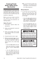
OPERATIONS Loading Framing Nailer Nail Size ...................... 1⁄8" Shank Diameter Nail Strip Angle.................34º Round Head Length..............................................2"–31⁄2" Magazine Capacity ........................ 60 Nails To load your framing nailer: 1. DISCONNECT NAILER FROM THE AIR SUPPLY! 2. Grip the nailer firmly and point the nose down, then pull the magazine pusher back until the catch lever engages, as shown in Figure 3. Figure 4. Loading nails into the magazine. 4.
3. Insert a strip of nails, pointed-end down, into the magazine as shown in Figure 6. 3. Depress the safety nose mechanism against your workpiece. 4. Before pulling the trigger, make sure your free hand and other body parts are positioned out of the way of a potential path of a nail in case of deflection. Figure 6. Loading nails into magazine (finish nailer). 4. Slide the nails all the way down to the nose of the nailer. 5.
Adjusting Nail Penetration Palm Nailer 1. Connect the air supply to the quick connect fitting. 2. Hold the nail firmly in place with one hand as if using a regular hammer. 3. Place the tip of the palm nailer over the top of the nail. When the ram pin touches the nail head, the nailer will automatically begin to hammer the nail into place. Note: Set the nail in position with a short burst of the nailer, then move your hand away from the nail before continuing. 4.
To adjust the nail penetration of your finish nailer: 3. Locate the opening in the underside of the nailer safety nose (see Figure 10). 1. DISCONNECT NAILER FROM THE AIR SUPPLY! 2. Rotate the depth adjustment knob (see Figure 9) clockwise to increase nail penetration, and counterclockwise to decrease nail penetration. Nose Opening Adjustment Knob Figure 10. Clearing a jammed nail. 4. Dislodge the jammed nail with a tool that will fit in the slot on the underside of the nose. Safety Nose Figure 9.
Nose Cover Nose Release Nose Tip Figure 11. Nose opened to clear a jam. 4. Dislodge the jammed nail with a tool that will fit in the slot on the underside of the nose. 5. Throw the damaged nail away and insert a new nail strip that only contains clean, undamaged nails. DO NOT use dirty or damaged nails! 6. Close the nose cover and replace the nose tip. Then release the catch lever and let the pusher slide to the front of the magazine.
7. Taking care not to scratch or dent the nailer parts, use a wooden dowel or similarly shaped tool to push the piston shaft back inside the nailer until you can grip the piston head and remove it from the cylinder. Clean and inspect the parts for cracks, wear, or burrs. 8. Apply a thin film of pneumatic tool oil on the new O-ring and place it on the new piston. 9. Insert the new piston in the cylinder.
CLEANING & LUBRICATION Cleaning Lubricating Use non-flammable solvent to clean the nose assembly of the nailer. Always be sure that the nailer is dry before using it again. Standard pneumatic tool oil has been included with your new Grizzly nailer to help maintain its useful life. Place two to six drops of oil in the nailer air inlet (as shown in Figure 12) before every use, or after 2 hours of continuous use. Do not allow dust, chips, sand, etc.
H8232 PARTS Framing Nailer Parts Breakdown �� � � � �� � � �� �� �� �� �� �� �� �� �� �� �� �� �� �� �� �� �� �� �� �� �� �� �� �� �� �� �� �� �� �� �� �� �� �� �� �� �� �� �� �� �� �� �� �� �� �� �� �� �� �� �� �� �� �� �� �� �� �� �� �� �� �� �� �� �� �� �� �� � �� �� �� �� � � �� �� �� � �� �� �� �� �� �� �� �� �� �� �� �� ���� �� �� ���� ���� -16- �� �� Model H8232 3-Piece Framing/Finish/Palm Nailer Kit
Framing Nailer Parts List REF PART # DESCRIPTION REF PART # DESCRIPTION 1 2 3 4 5 6 7 8 9 10 11 12 13 14 15 16 17 18 19 20 21 22 23 24 25 26 27 28 29 30 31 32 33 34 35 36 37 38 39 40 41 42 43 44 45 46 47 48 49 50 51 CAP SCREW M8-1.25 X 25 EXHAUST PORT SPACER CIRCULAR SPRING RETAINING RING CAP SCREW M6-1 X 25 LOCK WASHER 6MM CYLINDER PLUG SET SCREW M5-.8 X 5 CYLINDER COVER PISTON STOP SPRING SEAT COMPRESSION SPRING SPECIAL WASHER PISTON COLLAR O-RING 42.3 X 5 PISTON O-RING 54.4 X 3.
-18- ��� ��� ��� ��� ��� ��� ��� ��� ��� ��� ��� ��� ��� ��� ��� ��� ��� ��� ��� ��� ��� ��� ��� ��� ��� ��� ��� ��� ��� ��� ��� ��� ��� ��� ��� ��� ��� ��� ��� ��� ��� ��� ��� ��� ��� ��� ��� ��� ��� ��� ��� ��� ��� ��� ��� ��� ��� ��� ��� ��� ��� ��� ��� ��� ��� ��� ��� ��� ��� ��� ��� ��� ��� ��� ��� ��� ��� ��� ��� ��� ��� ��� ��� ��� ��� ��� ��� ��� ��� ��� ��� ��� ��� ��� ��� ��� ��� ��� ��� ��� ��� ��� ��� ��� Finish Nailer Parts Bre
Finish Nailer Parts List REF PART # DESCRIPTION REF PART # DESCRIPTION 101 102 103 104 105 106 107 108 109 110 111 112 113 114 115 116 117 118 119 120 121 122 123 124 125 126 127 128 129 130 131 132 133 134 135 136 137 138 139 140 141 142 143 144 145 146 147 148 SPECIAL BOLT EXHAUST PORT BUMPER WASHER CAP SCREW M5-.8 X 25 LOCK WASHER 5MM CYLINDER COVER O-RING 17.8 X 2.4 P18 COMPRESSION SPRING O-RING 24.7 X 3.5 P25 O-RING 37.7 X 3.5 P38 O-RING 48.7 X 3.5 P49 SWITCH VALVE O-RING 59.5 X 2.
Palm Nailer Parts Breakdown & List ��� ��� ��� ��� ��� ��� ��� ��� ��� ��� ��� ��� ��� ��� ��� ��� ��� ��� ��� ��� ��� ��� ��� ��� ��� ��� ��� ��� ��� ��� REF PART # DESCRIPTION REF PART # DESCRIPTION 201 202 203 204 205 206 207 208 209 210 211 212 213 214 CAP SCREW M5-.8 X 20 CAP O-RING 54.4 X 3.1 G50 RUBBER SEAL 54MM GASKET O-RING 54.4 X 3.1 G50 CYLINDER COLLAR SEALING RING CYLINDER CYLINDER COVER O-RING 39.4 X 3.1 G40 PISTON RAM PIN O-RING 59.4 X 3.
TROUBLESHOOTING Symptom Possible Cause Solution Air leaking at trig- 1. O-rings in trigger valve housing 1. O-rings must be replaced are damaged. & operation of safety nose ger valve area. must be checked. Air leaking. 1. Loose screws in housing. 2. Damaged O-ring(s). 3. Loose air fitting. 4. Damaged housing gasket(s). Tool skips nails 1. Excessive air pressure. 2. Air leaks. while discharging. 3. Dirt in nose. 4. Dirt or damage prevents nails from moving freely in magazine. 5.
WARRANTY AND RETURNS Grizzly Industrial, Inc. warrants every product it sells for a period of 1 year to the original purchaser from the date of purchase. This warranty does not apply to defects due directly or indirectly to misuse, abuse, negligence, accidents, repairs or alterations or lack of maintenance.