MODEL G0632 16" X 42" VARIABLE SPEED WOOD LATHE OWNER'S MANUAL (For models manufactured since 4/12) COPYRIGHT © APRIL, 2007 BY GRIZZLY INDUSTRIAL, INC. REVISED MARCH, 2015 (MN) WARNING: NO PORTION OF THIS MANUAL MAY BE REPRODUCED IN ANY SHAPE OR FORM WITHOUT THE WRITTEN APPROVAL OF GRIZZLY INDUSTRIAL, INC.
This manual provides critical safety instructions on the proper setup, operation, maintenance, and service of this machine/tool. Save this document, refer to it often, and use it to instruct other operators. Failure to read, understand and follow the instructions in this manual may result in fire or serious personal injury—including amputation, electrocution, or death. The owner of this machine/tool is solely responsible for its safe use.
Table of Contents INTRODUCTION................................................ 2 Manual Accuracy............................................ 2 Contact Info.................................................... 2 Machine Description....................................... 2 Identification.................................................... 3 Glossary Of Terms.......................................... 5 Machine Data Sheet....................................... 6 SECTION 1: SAFETY.................................
INTRODUCTION Manual Accuracy Contact Info We are proud to provide a high-quality owner’s manual with your new machine! We stand behind our machines. If you have any questions or need help, use the information below to contact us. Before contacting, please get the serial number and manufacture date of your machine. This will help us help you faster. We made every effort to be exact with the instructions, specifications, drawings, and photographs contained inside.
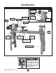
Identification Tailstock Handwheel Quill Tailstock Headstock Motor Faceplate Quill Lock Lever Headstock Lock Handle Quill Lock Handle Tool Rest Bed Control Panel Tool Rest Lock Handle Tool Rest Base Tool Rest Base Lock Handle Supporting Leg Figure 1. Model G0632 component identification. To reduce the risk of serious injury when using this machine, read and understand this entire manual before beginning any operations. Model G0632 (Mfg.
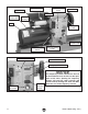
Frequency Inverter Safety Cover Front Belt Access Panel Control Panel Spindle Lock Motor Wiring Junction Box Spindle Handwheel Motor Indexing Pin Hole Headstock Rotation Lock Motor Mount Cap Screw Motor Tensioning Handle Figure 2. Model G0632 headstock. Front Belt Access Panel Spindle RPM Readout Emergency STOP Button NOTICE Variable Speed Dial Spindle Direction Switch The frequency inverter controls on the rear of the headstock have no effect on the operation of the lathe.
Glossary Of Terms The following is a list of common definitions, terms and phrases used throughout this manual as they relate to this wood lathe and turning in general. Become familiar with these terms for assembling, adjusting or operating this machine. Your safety is VERY important to us at Grizzly! Bed: The long, rail-like metal base to which the tailstock, tool base, and headstock are attached.
Machine Data Sheet Machine Data Sheet MACHINE DATA SHEET Customer Service #: (570) 546-9663 · To Order Call: (800) 523-4777 · Fax #: (800) 438-5901 MODEL G0632 16" X 42" VARIABLE-SPEED WOOD LATHE Product Dimensions: Weight.............................................................................................................................................................. 386 lbs. Width (side-to-side) x Depth (front-to-back) x Height...........................................................
Spindle Information Spindle Taper............................................................................................................................................ MT#2 Spindle Thread Size..................................................................................................................... 1-1/4" x 8 TPI Spindle Thread Direction.................................................................................................................. Right Hand Spindle Bore...................
Safety SECTION 1: SAFETY For Your Own Safety, Read Instruction Manual Before Operating This Machine The purpose of safety symbols is to attract your attention to possible hazardous conditions. This manual uses a series of symbols and signal words intended to convey the level of importance of the safety messages. The progression of symbols is described below. Remember that safety messages by themselves do not eliminate danger and are not a substitute for proper accident prevention measures.
WEARING PROPER APPAREL. Do not wear clothing, apparel or jewelry that can become entangled in moving parts. Always tie back or cover long hair. Wear non-slip footwear to avoid accidental slips, which could cause loss of workpiece control. HAZARDOUS DUST. Dust created while using machinery may cause cancer, birth defects, or long-term respiratory damage. Be aware of dust hazards associated with each workpiece material, and always wear a NIOSH-approved respirator to reduce your risk. HEARING PROTECTION.
Additional Safety for Wood Lathes KEEPING GUARDS IN PLACE. Make sure all guards are in place and that the lathe sits on a flat, stable surface. EYE/FACE PROTECTION. Airborne wood dust and debris can be hazardous to the eyes/face and may cause allergies or long-term respiratory health problems. Always wear eye protection or a face shield when operating the lathe. RESPIRATORY PROTECTION. Always wear a respirator when using this machine. Wood dust may cause allergies or long-term respiratory health problems.
Circuit Requirements SECTION 2: POWER SUPPLY Availability Circuit Requirements for 220V Before installing the machine, consider the availability and proximity of the required power supply circuit. If an existing circuit does not meet the requirements for this machine, a new circuit must be installed.
Grounding Requirements This machine MUST be grounded. In the event of certain malfunctions or breakdowns, grounding reduces the risk of electric shock by providing a path of least resistance for electric current. Improper connection of the equipment-grounding wire can result in a risk of electric shock. The wire with green insulation (with or without yellow stripes) is the equipment-grounding wire.
SECTION 3: SETUP Unpacking This machine presents serious injury hazards to untrained users. Read through this entire manual to become familiar with the controls and operations before starting the machine! This machine and its components are very heavy. Get lifting help or use power lifting equipment such as a forklift to move heavy items. Needed for Setup Your machine was carefully packaged for safe transportation. Remove the packaging materials from around your machine and inspect it.
Inventory Inventory The following is a list of items shipped with your machine. Before beginning setup, lay these items out and inventory them. B If any non-proprietary parts are missing (e.g. a nut or a washer), we will gladly replace them; or for the sake of expediency, replacements can be obtained at your local hardware store. Box Inventory: (Figures 5–7) Qty A. Lathe Assembly —Headstock (mounted).............................. 1 —Tool Rest Base (mounted)....................... 1 —Tailstock (mounted)..
Clean Up Cleanup The unpainted surfaces of your machine are coated with a heavy-duty rust preventative that prevents corrosion during shipment and storage. This rust preventative works extremely well, but it will take a little time to clean. Be patient and do a thorough job cleaning your machine. The time you spend doing this now will give you a better appreciation for the proper care of your machine's unpainted surfaces.
Site Considerations Weight Load Physical Environment Refer to the Machine Data Sheet for the weight of your machine. Make sure that the surface upon which the machine is placed will bear the weight of the machine, additional equipment that may be installed on the machine, and the heaviest workpiece that will be used. Additionally, consider the weight of the operator and any dynamic loading that may occur when operating the machine.
Mounting to Shop Floor Mounting to Shop Floor Although not required, we recommend that you bolt your new lathe to the floor. Because this is an optional step and floor materials may vary, machine feet are included with your lathe. Generally, you can either bolt your machine to the floor or mount it on the included machine feet. Whichever option you choose, we recommend leveling your machine with a precision level. Assembly To assemble your lathe: 1.
3. Secure the lathe assembly to the supporting legs with the (8) M10-1.5 x 25 cap screws and 10mm flat washers (see Figure 12). 6. Figure 12. Securing lathe assembly to supporting legs. 4. If you are bolting your lathe to the floor, skip to Step 7. Otherwise, move the tailstock, tool rest assembly, and headstock to one end of the lathe bed (see the OPERATIONS section beginning on Page 21 for instructions for moving these components). 5.
Power Connection After you have completed all previous setup instructions and circuit requirements, the machine is ready to be connected to the power supply. Disconnecting Power 1. Turn the machine power switch OFF. 2. Grasp the molded plug and pull it completely out of the receptacle. Do not pull by the cord as this may damage the wires inside. To avoid unexpected startups or property damage, use the following steps whenever connecting or disconnecting the machine. Connecting Power 1.
Test Run 4. Once the assembly is complete, test run your machine to make sure it runs properly and is ready for regular operation. The test run consists of verifying the following: 1) The motor powers up and runs correctly and 2) the stop button safety feature works correctly. TWIST To Reset Switch... If, during the test run, you cannot easily locate the source of an unusual noise or vibration, stop using the machine immediately, then review Troubleshooting on Page 39.
Operations SECTION 4: OPERATIONS Operation Overview To reduce the risk of serious injury when using this machine, read and understand this entire manual before beginning any operations. Damage to your eyes and lungs could result from using this machine without proper protective gear. Always wear a face shield and respirator when operating this machine.
8. Verifies the spindle direction switch is in the center neutral position and the spindle speed dial is turned all the way counterclockwise so the spindle does not start turning at high speed. 9. Ties back loose hair and clothing, and puts on face shield and respirator. Takes all other required safety precautions. 10.
Adjusting Tailstock To swivel the headstock: 1. DISCONNECT THE LATHE FROM THE POWER SOURCE! 2. Loosen the headstock lock handle (see Figure 20). 3. Pull the swivel pin out and rotate the headstock to the desired position (see Figure 21). The tailstock is equipped with a cam-action clamping system to secure it to the lathe bed. When the lever is tightened, a locking plate lifts up underneath the bed and secures the tailstock in place. To position the tailstock along the length of the bed: 1.
Adjusting Tool Rest The tool rest base is equipped with a cam-action clamping system to secure it to the lathe bed. When the tool rest base lock handle is tightened, a locking plate lifts up and secures the tool rest assembly to the bed. The tool rest can also be positioned and locked at a specific angle or height. To position the tool rest assembly along the length of the lathe bed: 1. Always operate the lathe with the tool rest assembly firmly locked in position.
Headstock Center Installing/Removing Headstock Center 5. Make sure the center is securely installed by attempting to pull it out by hand—a properly installed center will not pull easily. To remove the headstock center with the knockout tool: Make sure the headstock and tailstock centers are properly aligned before beginning any turning operation. See Aligning Centers on Page 41 for additional instructions on this procedure.
Tailstock Center Installing/Removing Tailstock Center The included live center installs into the tailstock quill with an MT#2 tapered fit. To install the center into the tailstock quill: 1. Loosen the quill lock handle and rotate the tailstock handwheel until the quill extends out about 1" (see Figure 27). Quill Keyway Quill Lock Handle Figure 28. Quill lock handle aligned with quill keyway. Quill Lock Handle 6. Secure the quill in place by re-tightening the quill lock handle.
Headstock Faceplate Headstock Faceplate To mount a workpiece to the faceplate, refer to Faceplate Turning on Page 35. 4. Using the included 4mm hex wrench, tighten the three set screws along the inside diameter of the faceplate to secure it to the spindle (see Figure 30). The faceplate can be installed only if the headstock center has been removed. To install the headstock faceplate: 1. DISCONNECT THE LATHE FROM THE POWER SOURCE! 2.
Changing Speed Ranges Changing Speed Ranges The Model G0632 has two speed ranges: 1) the low range from 100 to 1200 RPM which provides a greater torque, and 2) the high range from 250 to 3200 RPM. To change speed ranges: 1. DISCONNECT THE LATHE FROM THE POWER SOURCE! 2. Remove the front belt access panel (see Figure 32). Refer to the speed recommendations table (see Figure 31) to choose the appropriate RPM for your operation. Then choose the speed range that will include the selected RPM.
4. 5. Use the motor tensioning handle to lift the motor assembly all the way up and re-tighten the motor mount cap screw—this will hold the motor in place while you change the belt position. 6. Loosen the motor mount cap screw and lower the motor. 7. Apply downward pressure on the motor tensioning handle to properly tension the drive belt and re-tighten the motor mount cap screw. Reach into the belt access cavity and roll the belt onto the desired set of pulleys (see Figure 34).
Indexing Indexing on a lathe is typically used for workpiece layout and other auxiliary operations that require equal distances around the workpiece circumference, such as clock faces or inlays. To use the indexing feature, place the indexing pin into one of the indexing holes in the headstock as shown in Figure 37. This will hold the spindle and workpiece at the desired indexed position.
Selecting Turning Tools • Lathe tools come in a variety of shapes and sizes, and usually fall into five major categories. • Scrapers—Typically used where access for other tools is limited, such as hollowing operations. This is a flat, double-ground tool that comes in a variety of profiles (round nose, spear point, square nose, etc.) to match many different contours. Gouges—Mainly used for rough cutting, detail cutting, and cove profiles.
Spindle Turning Spindle Turning To set up a spindle turning operation: 1. Spindle turning is the operation performed when a workpiece is mounted between the headstock and the tailstock (see Figure 42). Find the center point of both ends of your workpiece by drawing diagonal lines from corner to corner across the end of the workpiece (see Figure 43). Workpiece Pencil Lines Marked Diagonally Across Corners Workpiece Center Figure 42. Typical spindle turning operation. Figure 43.
4. To help embed the spur center into the workpiece, cut 1⁄8" deep saw kerfs in the same end of the workpiece along the diagonal lines marked in Step 1. 8. Install the live center into the tailstock quill and tighten the quill lock handle to lock the quill in position (refer to Page 26 for additional instructions). 5. If your workpiece is over 2" x 2", cut the corners off the workpiece length-wise to make turning safer and easier. 9. 6.
Tool Rest 11. Position the tool rest approximately 1⁄4" away from the workpiece and approximately 1⁄8" above the workpiece center line (see Figure 45). 1 ⁄4" ⁄8" • When turning the lathe ON, stand away from the path of the spinning workpiece until the lathe reaches full speed and you can verify that the lathe will not throw the workpiece. • Use the slowest speed when starting or stopping the lathe.
Faceplate Turning Faceplate Turning Faceplate turning is when a workpiece is mounted to the faceplate, which is then mounted to the headstock spindle. This type of turning is usually done with open-faced workpieces like bowls or plates. NOTICE Only use tap screws or wood screws with non-tapered heads (Figure 48) to attach the faceplate to the workpiece. Do NOT use drywall screws or screws with tapered heads because they can split the faceplate, or the screws may snap off during operation.
Outboard Turning Sanding/Finishing Outboard turning is a variation of faceplate turning and is usually done when the stock diameter is greater than 12". For the size of this particular lathe and its minimum turning speed, we recommend a maximum diameter of 17". After the turning operations are complete, the workpiece can be sanded and finished before removing it from the lathe (see Figure 50). Figure 49 depicts the lathe setup at 90° for turning larger workpieces.
ACCESSORIES SECTION 5: ACCESSORIES G1194—3-Jaw Chuck A "must have" for the serious wood turner. This 3-jaw chuck is a self-centering style chuck used mostly for round work. All three jaws tighten together at the same time. Jaws are reversible for expanded work holding capacity. Threaded insert required for mounting! T10117—Big Mouth Dust Hood with Stand Capture dust from any machine operation with this Big Mouth Dust Hood.
SECTION 6: MAINTENANCE Lathe Bed Always disconnect power to the machine before performing maintenance. Failure to do this may result in serious personal injury. Schedule For optimum performance from your machine, follow this maintenance schedule and refer to any specific instructions given in this section. Daily Check: • Loose mounting bolts. • Damaged centers or faceplate. • Worn or damaged wires. Any other unsafe condition. • Weekly Maintenance: • Clean off dust buildup.
SECTION 7: SERVICE Troubleshooting Review the troubleshooting and procedures in this section to fix or adjust your machine if a problem develops. If you need replacement parts or you are unsure of your repair skills, then feel free to call our Technical Support at (570) 546-9663. Troubleshooting Motor & Electrical Symptom Possible Cause Machine does not 1. Emergency stop push-button is engaged/ start or a breaker faulty. trips. 2. Motor connection wired incorrectly. 3. FWD/REV switch is at fault. 4.
Wood Lathe Operation SYMPTOM POSSIBLE CAUSE CORRECTIVE ACTION Vibration noise while machine is running; noise changes when speed is changed. 1. Belt cavity cover(s) loose. 1. Tighten the screws that mount the belt cavity cover(s); if necessary install a soft, vibration dampening material between the belt cover and the headstock casting. Vibration noise while machine is running; noise remains constant when speed is changed. 1. Dented fan cover on motor. 1. Replace or adjust fan cover.
Aligning Centers Changing V-Belt Aligning Centers Front Belt Access Panel To ensure accurate and safe turning results, the headstock and tailstock centers must be aligned with one another. To align the centers: 1. 2. With the headstock and tailstock centers installed, slide the tailstock up to the headstock. Loosen the headstock lock handle and swivel the headstock so the tip of the centers touch, as illustrated in Figure 55, then lock the headstock in place. Figure 55.
machine SECTION 8: WIRING These pages are current at the time of printing. However, in the spirit of improvement, we may make changes to the electrical systems of future machines. Compare the manufacture date of your machine to the one stated in this manual, and study this section carefully. If there are differences between your machine and what is shown in this section, call Technical Support at (570) 546-9663 for assistance BEFORE making any changes to the wiring on your machine.
Electrical Components Electrical Components Variable Speed Control REV/FWD Switch Emergency Stop Button RPM Sensor RPM Readout & Circuit Board Figure 58. Model G0632 control panel wiring (shown from the back of the panel). Figure 60. Model G0632 RPM sensor wiring. Figure 59. Model G0632 motor junction box wiring. Figure 61. Model G0632 frequency inverter wiring. Model G0632 (Mfg.
Wiring Diagram Overview Wiring Diagram (Wiring Page 45) (Figure 59, Page 43) Frequency Inverter 220V, 1-Phase Ground G Hot Gn Wt Bl U1 Bk V1 Bk W1 Bk U2 V2 Hot Bl 6-15 Plug (As Recommended) Br Gn W2 Bk Ground Motor 220V, 3-Phase Control Panel (as viewed from the back) (Figure 59, Page 43) (Figure 58, Page 43) Bl Gn Bk Br RPM Sensor (Figure 60, Page 43) Wt Rd Yl Bl Wt Bl Wt Bk Wt Wt Wt Br Rd Wt Variable Speed Control REV/FWD Switch Emergency RPM Readout Stop & Circuit
Inverter Wiring Frequency Inverter Wiring Diagram 220V, 1-Phase Ground G Hot Gn Wt Bl Hot Breaking Resistor Frequency Inverter +10V AVI AFM M0 I M1 M2 M3 6-15 Plug (As Recommended) M4 M5 GND V Gn Yl Wt Bk Bl Br Rd Wt Bk Bk Br Bl Gn Bk Wt Gn Bk Bk Yl Rd Bl Wt Gn Bk Br R2 Gn R1 Bk Bk Bk Bl Br To Controls Model G0632 (Mfg. Since 1/09+) View this page in color at www.grizzly.com.
SECTION 9: PARTS Stand Breakdown 21 19 22 16 20-1 17 11 17 15 12 7 29 20 9 8 23 24 14 13 10 6 6 5 5 4V2 3 25 2 26 27 28 1 -46- Model G0632 (Mfg.
Stand Parts List REF PART # DESCRIPTION REF PART # DESCRIPTION 1 2 3 4V2 5 6 7 8 9 10 11 12 13 14 15 SUPPORTING LEG BED BUSHING TOOL REST BASE LOCK BRACKET V2.02.
59-1 -48- 60 61 59-4 48-1 61-1 59 51 61-2 61-3 63 62 59-2 50 52 61-5 67 56 55 45 61-8 61-6 61-7 61-9 68 69 54 44V2 74 42 72 73 71 70 43 44V2-1 44AV2 46 44V2-2 53 59-3 66 58 61-4 64 65 57 49 48 47 105 75 78 79 77 98 40 104 103 39 38 108 107 76 106 41 80 37 81 93 82 83 84 95 96 97 36 91A 35 85 86 87 88 34 109 91 92 33 32 123 122 31 Headstock Breakdown Model G0632 (Mfg.
Headstock Parts List REF PART # DESCRIPTION REF PART # DESCRIPTION 31 32 33 34 35 36 37 38 39 40 41 42 43 44 44AV2 44V2 44V2-1 44V2-2 45 46 47 48 48-1 49 50 51 52 53 54 55 56 57 58 59 59-1 59-2 59-3 59-4 60 61 61-1 61-2 61-3 61-4 61-5 61-6 61-7 P0632031 P0632032 P0632033 P0632034 P0632035 P0632036 P0632037 P0632038 P0632039 P0632040 P0632041 P0632042 P0632043 P0632044 P0632044AV2 P0632044V2 P0632044V2-1 P0632044V2-2 P0632045 P0632046 P0632047 P0632048 P0632048-1 P0632049 P0632050 P0632051 P0632052 P0
Label Placement 115 118 111 114 112 113 116 110 120 119 117 REF PART # DESCRIPTION REF PART # DESCRIPTION 110 111 112 113 114 115 MACHINE ID LABEL READ MANUAL 2W X 3.3H V2.07.05 ENTANGLEMENT HAZARD 3.8 X 2H GLASSES/RESPIRATOR 3.
WARRANTY AND RETURNS Grizzly Industrial, Inc. warrants every product it sells for a period of 1 year to the original purchaser from the date of purchase. This warranty does not apply to defects due directly or indirectly to misuse, abuse, negligence, accidents, repairs or alterations or lack of maintenance.
WARRANTY CARD Name _____________________________________________________________________________ Street _____________________________________________________________________________ City _______________________ State _________________________ Zip _____________________ Phone # ____________________ Email _________________________________________________ Model # ____________________ Order # _______________________ Serial # __________________ The following information is given on a voluntary basis.
FOLD ALONG DOTTED LINE Place Stamp Here GRIZZLY INDUSTRIAL, INC. P.O.