MODEL G0739 OSCILLATING SPINDLE SANDER OWNER'S Manual (For models manufactured since 2/12) Copyright © FEBRUARY, 2012 By Grizzly Industrial, Inc. Warning: No portion of this manual may be reproduced in any shape Or form without the written approval of Grizzly Industrial, inc.
This manual provides critical safety instructions on the proper setup, operation, maintenance, and service of this machine/tool. Save this document, refer to it often, and use it to instruct other operators. Failure to read, understand and follow the instructions in this manual may result in fire or serious personal injury—including amputation, electrocution, or death. The owner of this machine/tool is solely responsible for its safe use.
Table of Contents INTRODUCTION................................................ 2 Manual Accuracy............................................ 2 Contact Info.................................................... 2 Identification.................................................... 3 SECTION 4: OPERATIONS............................ 16 Disabling Switch........................................... 16 Sanding Drum/Sleeve Installation................. 17 Sanding........................................................
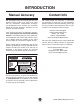
INTRODUCTION Manual Accuracy Contact Info We are proud to offer this manual with your new machine! We've made every effort to be exact with the instructions, specifications, drawings, and photographs of the machine we used when writing this manual. However, sometimes we still make an occasional mistake. We stand behind our machines. If you have any questions or need help, use the information below to contact us. Before contacting, please get the serial number and manufacture date of your machine.
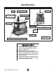
Identification Spindle Spindle Hex Nut Table Insert Spindle Washer Drum and Sanding Sleeve Table Sander Body Dust Port Drums and Sanding Sleeves Power Cord Table Inserts ON/OFF Paddle Switch w/Disabling Key Spindle Washers (Not Shown) Figure 1. Machine identification. for your Own Safety Read This Manual before Operating Spindle Sander a) Wear eye protection. b) Support workpiece on worktable. c) Minimize pinch hazards. use the smallest table insert possible with sanding drum. d) Avoid kickback.
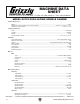
MACHINE DATA SHEET Customer Service #: (570) 546-9663 · To Order Call: (800) 523-4777 · Fax #: (800) 438-5901 MODEL G0739 OSCILLATING SPINDLE SANDER Product Dimensions: Weight............................................................................................................................................................... 30 lbs. Width (side-to-side) x Depth (front-to-back) x Height.................................................. 15-9/16 in. x 14-1/8 in. x 17 in. Footprint (Length x Width)....
SECTION 1: SAFETY For Your Own Safety, Read Instruction Manual Before Operating this Machine The purpose of safety symbols is to attract your attention to possible hazardous conditions. This manual uses a series of symbols and signal words intended to convey the level of importance of the safety messages. The progression of symbols is described below. Remember that safety messages by themselves do not eliminate danger and are not a substitute for proper accident prevention measures.
DISCONNECTING POWER SUPPLY.Alwaysdisconnect machine from power supply before servicing, adjusting, or changing cutting tools (bits, blades, cutters, etc.). Make sure switch is in OFF positionbeforereconnectingtoavoidanunexpectedorunintentionalstart. APPROVED OPERATION. Untrained operators can be seriously hurt by machinery. Only allow trained or properly supervised people to use machine.
Additional Safety for Spindle Sanders FEED RATE. Never jam a workpiece against the sanding surface. This can cause the workpiece to kick back or damage the machine. Firmly hold the workpiece and ease it against the spindle using light pressure. DUST COLLECTION. Never operate the sander without an adequate dust collection system in place and running. Proper dust collection reduces dust in the work area, which decreases the risk of long-term respiratory damage. AVOIDING ENTANGLEMENT.
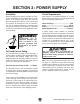
SECTION 2: POWER SUPPLY Availability Circuit Requirements Before installing the machine, consider the availability and proximity of the required power supply circuit. If an existing circuit does not meet the requirements for this machine, a new circuit must be installed. To minimize the risk of electrocution, fire, or equipment damage, installation work and electrical wiring must be done by a qualified electrician in accordance with all applicable codes and standards.
Polarized Plug Extension Cords To reduce the risk of electric shock, this machine has a polarized plug (one blade is wider than the other). This plug will fit in a polarized outlet only one way. If the plug does not fit fully in the outlet, turn it 180 degrees and try again. If it still does not fit, contact a qualified electrician to install the proper outlet. Do not change the plug in any way. We do not recommend using an extension cord with this machine.
SECTION 3: SETUP Unpacking This machine presents serious injury hazards to untrained users. Read through this entire manual to become familiar with the controls and operations before starting the machine! Wear safety glasses during the entire setup process! Needed for Setup The following are needed to complete the setup process, but are not included with your machine. Your machine was carefully packaged for safe transportation. Remove the packaging materials from around your machine and inspect it.
Inventory Cleanup The following is a description of the main components shipped with your machine. Lay the components out to inventory them. The unpainted surfaces of your machine are coated with a heavy-duty rust preventative that prevents corrosion during shipment and storage. This rust preventative works extremely well, but it will take a little time to clean. If any non-proprietary parts are missing (e.g.
Site Considerations Weight Load Physical Environment Refer to the Machine Data Sheet for the weight of your machine. Make sure that the surface upon which the machine is placed will bear the weight of the machine, additional equipment that may be installed on the machine, and the heaviest workpiece that will be used. Additionally, consider the weight of the operator and any dynamic loading that may occur when operating the machine.
Mounting The base of this machine has mounting holes that allow it to be fastened to a workbench or other mounting surface to prevent it from moving during operation and causing accidental injury or damage. Assembly Place the spindle hex nut, table inserts, sanding drums and sleeves, and spindle washers in the appropriate sized accessory slots beneath the table. A sanding drum does not need to be installed until after the test run.
Dust Collection DO NOT operate the Model G0739 without an adequate dust collection system. This sander creates substantial amounts of wood dust while operating. Failure to use a dust collection system can result in short and long-term respiratory illness. Recommended CFM at Dust Port: 100 CFM Do not confuse this CFM recommendation with the rating of the dust collector.
where children may be present. Test Run IMPORTANT: Disabling the switch only restricts its function. It is not a substitute for disconnecting machine fromkey, power when 6. Remove the switch disabling as shown adjusting or servicing. in Figure 11. Once the assembly is complete, test run your machine to make sure it runs properly and is ready for regular operation. Note: You do not need to install a drum to perform the test run.
SECTION 4: OPERATIONS Disabling Switch To reduce the risk of serious injury when using this machine, read and understand this entire manual before operating. Damage to your eyes and lungs could result from using this machine without proper protective gear. Always wear safety glasses and a respirator when operating this machine. The switch The switch can can be be disabled disabled by by removing removing the the key, key, as shown in the following figure. Disabling the as shown below.
Sanding Drum/ Sleeve Installation To ensure the workpiece is supported during sanding operations, use the table insert that matches the corresponding drum and sleeve (see table below). It is important to keep the gap between the table insert and drum as small as possible to reduce the risk of a pinch hazard. Sanding Sleeves Sanding Drums ⁄2" N/A 1 ⁄4" 1 ⁄4" Table Inserts 4. Clean the table opening for the table insert and any other spindle areas as necessary.
ACCESSORIES SECTION 5: ACCESSORIES Some aftermarket accessories can be installed on this machine that could cause it to function improperly, increasing the risk of serious personal injury. To minimize this risk, only install accessories recommended for this machine by Grizzly. NOTICE Replacement Sanding Sleeve 3 Packs H5434—1 ⁄ 2" Dia. x 41 ⁄ 2", Hard A150 H5438— 3 ⁄4" Dia. x 41 ⁄ 2", Hard A120 H5442—1" Dia. x 41 ⁄ 2", Hard A100 H5447—11 ⁄ 2" Dia. x 41 ⁄ 2", Hard A100 H5451—2" Dia.
SECTION 6: MAINTENANCE Cleaning Always disconnect power to the machine before performing maintenance. Failure to do this may result in serious personal injury. Schedule For optimum performance from your machine, follow this maintenance schedule and refer to any specific instructions given in this section. To clean your machine, vacuum excess wood chips and sawdust, and wipe off any remaining dust with a dry cloth.
SECTION 7: SERVICE Review the troubleshooting and procedures in this section if a problem develops with your machine. If you need replacement parts or additional help with a procedure, call our Technical Support at (570) 546-9663. Note: Please gather the serial number and manufacture date of your machine before calling. Troubleshooting Symptom Possible Cause Possible Solution Motor will not start. 1. Switch disabling key removed. 2. Loose connections at motor or switch. 1. Insert key to enable switch.
Changing Motor Brushes Tools Required: Qty Screwdriver Phillips #2.................................1 To change motor brushes: 1. DISCONNECT SANDER FROM POWER. This sander has a permanent magnet motor that uses carbon brushes for operation. These brushes normally wear out over time and eventually need to be replaced.
machine SECTION 8: WIRING These pages are current at the time of printing. However, in the spirit of improvement, we may make changes to the electrical systems of future machines. Compare the manufacture date of your machine to the one stated in this manual, and study this section carefully. If there are differences between your machine and what is shown in this section, call Technical Support at (570) 546-9663 for assistance BEFORE making any changes to the wiring on your machine.
Wiring Diagram G0739 Wiring Diagram Motor 120V PADDLE SWITCH (Viewed from Behind) 120 VAC 1-15 Plug + Single-Phase Silicon Bridge Rectifier KBPC1504 Model G0739 (Mfg.
SECTION 9: PARTS Main Breakdown 13 41 16 14 1 17 15 2 (2-1, 2-2, 2-3) 43 42 18 19 7 3 (3-1, 3-2, 3-3, 3-4, 3-5, 3-6) 45 66 46 20 21 4 (4-1, 4-2, 4-3, 4-4, 4-5) 44 47 48 67 50 22 49 51 52 23 68 24 69 25 8 5 (5-1, 5-2, 5-3, 5-4, 5-5, 5-6) 6 26 9 53 71 70 30 54 72 55 27 75 76 73 56 10 11 28 12 32 29 31 33 39 74 36 37 38 34 35 33A 57 59 60 40 77 78 61 28A 79 62 80 82 83 89 86 63 64 87 88 84 85 58 65 81 39 90 91 -24- Model G0739 (Mfg.
Main Parts List REF PART # DESCRIPTION REF PART # DESCRIPTION 1 2 2-1 2-2 2-3 3 3-1 3-2 3-3 3-4 3-5 3-6 4 4-1 4-2 4-3 4-4 4-5 5 5-1 5-2 5-3 5-4 5-5 5-6 6 7 8 9 10 11 12 13 14 15 16 17 18 19 20 21 22 23 24 25 26 27 28A 28 29 30 31 32 33A 33 34 35 SPINDLE HEX NUT M10-1.
Labels Breakdown REF PART # DESCRIPTION REF PART # DESCRIPTION 92 93 WARNING LABEL ID LABEL 94 99 MACHINE HAZARDS LABEL ELECTRICITY LABEL P0739092 P0739093 P0739094 PLABEL-14A Safety labels help reduce the risk of serious injury caused by machine hazards. If any label comes off or becomes unreadable, the owner of this machine MUST replace it in the original location before resuming operations. For replacements, contact (800) 523-4777 or www.grizzly.com.
WARRANTY CARD Name _____________________________________________________________________________ Street _____________________________________________________________________________ City _______________________ State _________________________ Zip _____________________ Phone # ____________________ Email ________________________ Invoice # _________________ Model # ____________________ Order # _______________________ Serial # __________________ The following information is given on a voluntary basis.
FOLD ALONG DOTTED LINE Place Stamp Here GRIZZLY INDUSTRIAL, INC. P.O.
WARRANTY & RETURNS Grizzly Industrial, Inc. warrants every product it sells for a period of 1 year to the original purchaser from the date of purchase. This warranty does not apply to defects due directly or indirectly to misuse, abuse, negligence, accidents, repairs or alterations or lack of maintenance.
Buy Direct and Save with Grizzly ® – Trusted, Proven and a Great Value! ~Since 1983~ Visit Our Website Today For Current Specials! ORDER 24 HOURS A DAY! 1-800-523-4777