ROUTER TABLE MODEL G0528 INSTRUCTION MANUAL COPYRIGHT © SEPTEMBER, 2003 BY GRIZZLY INDUSTRIAL, INC. WARNING: NO PORTION OF THIS MANUAL MAY BE REPRODUCED IN ANY SHAPE OR FORM WITHOUT THE WRITTEN APPROVAL OF GRIZZLY INDUSTRIAL, INC. #TR5457 REVISED MAY, 2004.
WARNING Some dust created by power sanding, sawing, grinding, drilling, and other construction activities contains chemicals known to the State of California to cause cancer, birth defects or other reproductive harm. Some examples of these chemicals are: • Lead from lead-based paints. • Crystalline silica from bricks, cement, and other masonry products. • Arsenic and chromium from chemically treated lumber. Your risk from these exposures varies, depending on how often you do this type of work.
Table of Contents SECTION 1: SAFETY ....................................................................................................................... 2 Safety Instructions For Power Tools .......................................................................................... 2 Additional Safety Instructions For Router Tables....................................................................... 4 SECTION 2: INTRODUCTION ..............................................................................
SECTION 1: SAFETY For Your Own Safety Read Instruction Manual Before Operating This Equipment The purpose of safety symbols is to attract your attention to possible hazardous conditions. This manual uses a series of symbols and signal words which are intended to convey the level of importance of the safety messages. The progression of symbols is described below. Remember that safety messages by themselves do not eliminate danger and are not a substitute for proper accident prevention measures.
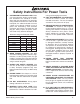
Safety Instructions For Power Tools 9. USE PROPER EXTENSION CORD. Make sure your extension cord is in good condition. Conductor size should be in accordance with the chart below. The amperage rating should be listed on the motor or tool nameplate. An undersized cord will cause a drop in line voltage resulting in loss of power and overheating. Your extension cord must also contain a ground wire and plug pin. Always repair or replace extension cords if they become damaged.
Additional Safety Instructions For Router Tables 1. HAND POSITIONING. Never pass your hands directly over or in front of the cutter. As one hand approaches cutter, move it in an arc motion away from the cutter to the outfeed side and reposition that hand beyond the cutter. 2. STOCK LENGTH. Do not rout stock shorter than 12 inches without special fixtures or jigs. Where practical, rout longer stock and cut to size. 3. BLIND CUT WHENEVER POSSIBLE.
SECTION 2: INTRODUCTION Commentary Lack of familiarity with this manual could cause serious personal injury. Become familiar with the contents of this manual, including all the safety warnings. We are proud to offer the Model G0528 Router Table. This machine is part of a growing Grizzly family of fine woodworking machinery. When used according to the guidelines set forth in this manual, you can expect years of trouble-free, enjoyable operation and proof of Grizzly’s commitment to customer satisfaction.
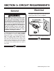
SECTION 3: CIRCUIT REQUIREMENTS General Electrical The power switch plugs into a wall outlet that is properly grounded as shown in Figure 1. If the machine is wired incorrectly a fire could result. Make sure your wiring, receptacle, plug, and circuit breaker can handle the current draw of the machine. If you are not sure that your electrical circuit can handle the current draw, get a qualified electrician to test your electrical system and do any required upgrades.
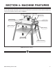
SECTION 4: MACHINE FEATURES Set up and operation instructions will be easier to understand if you become familiar with the location and names of the machine features shown in Figure 2. Workpiece Hold-Downs Dust Port Infeed Fence Outfeed Fence Main Table Sliding Table Miter Gauge Power Switch Table Tilt Brackets Figure 2. Machine features.
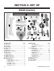
SECTION 5: SET UP G0528 Inventory F Q M A E H P S I R K B C D L N O G J Figure 3. G0528 Inventory. DESCRIPTION QTY A. Left Fence .....................................................1 B. Right Fence ...................................................1 C. Dust Hood .....................................................1 D. Power Cord ...................................................1 E. Switch ............................................................1 F. Switch Box.........................
10 2 ⁄ '' 12 23⁄4'' 3 WASH S WA H ASH DIA ER 8mm ASH W ASHE 6mm DI ER ASH R DIA ⁄ '' 14 D ER I ASH 21⁄4'' ⁄ '' 5 16 ET AM LINES ARE 1⁄16'' INCH APART LINES ARE 1MM APART 2 10mm R DIA ET AM 1 ⁄ '' 34 4mm MET 11⁄2'' D ER IA ⁄ '' 38 METE G0528 Sliding Router Table ⁄ '' ⁄ '' ⁄ '' ⁄ '' ⁄ '' 1'' 11⁄4'' 5 16 7 16 9 16 34 78 TE ME R 16mm '' '' '' '' MET 12mm ⁄ ⁄ ⁄ ⁄ 14 38 12 58 DI ER ETER M 10mm 5mm 10mm 15mm 20mm 25mm 30mm 35mm 40mm 45mm 50mm 55mm 60mm 65mm 70mm 75mm
Clean Up Site Considerations Metal components are often coated with a wax or oil to prevent rusting during shipment. Clean all coated parts with a solvent cleaner or citrus-based degreaser such as Grizzly’s G7895 Degreaser. To clean thoroughly, some parts may need to be removed. For optimum performance from your machine, make sure you clean all moving parts or sliding contact surfaces that are coated. Avoid chlorine-based solvents as they may damage painted surfaces should they come in contact.
Assembly Rubber Feet This section covers the basic assembly and adjustment instructions needed to begin operation. Complete the assembly in the order provided in this manual and then read the remaining portion of the manual before attempting any type of operation. Components Needed: Qty Rubber Feet .......................................................4 Phillips Screws 1⁄4"-20 x 1" .................................4 Hex Nuts 1⁄4"-20 ..................................................4 Flat Washers 1⁄4" .
Cross Supports Components Needed: Qty Table Assembly ..................................................1 Table Cross Supports.........................................3 Rubber Stops .....................................................2 Cap Screws 5⁄16"-18 x 11⁄2" ..................................2 Flat Washers 5⁄16" ................................................8 Hex Nuts 5⁄16"-18 .................................................4 Hex Bolts 5⁄16"-18 x 1" .........................................2 3.
Stand Table Braces Components Needed: Qty Stand Legs .........................................................4 Diagonal Supports ..............................................2 Tray ....................................................................1 Carriage Bolts 5⁄16"-18 x 1⁄2" ...............................32 Flat Washers 5⁄16" ..............................................32 Lock Washers 5⁄16" ............................................32 Hex Nuts 5⁄16"-18 ........................................
Fence Hold-Downs Components Needed: Qty Left Fence .........................................................1 Components Needed: Qty Workpiece Hold-Down Assemblies ....................2 Right Fence ........................................................1 Dust Hood ..........................................................1 Fence Lock Handles...........................................2 Tools Needed: 19mm Wrench ....................................................
Miter Router To Table Components Needed: Qty Miter Fence ........................................................1 Miter Plate ..........................................................1 Components Needed: Qty Router Clamps ...................................................4 To attach the sliding table: 1. Secure the miter plate to the sliding table by sliding the T-bolts into the table T-track. 2. Position the miter plate in the desired position and tighten the threaded star knobs.
3. Loosen the router clamps enough to allow the base of the router to press flat against the underside of the cast iron table. Note—The router spindle should be centered under the cut out in the cast iron table. 4. Adjust the thickness bolts and the jam nuts on each of the router clamps to allow the router base to be secured against the table (Figure 14). Jam Nut Switch Qty Components Needed: Switch .................................................................1 Switch Box...........................
5. Attach the black and white power wires to the back of the switch (Figure 15), at the clips labeled “B” and “W." Dust Port Hook-Up DO NOT use the router table without adequate dust collection. Hook the dust port up to a shop vacuum or dust collection system. Figure 15. Securing the power wires to the switch. 6. Secure the switch box to the back of the switch using the Phillips head screws, the external toothed washers, and the hex nuts already installed in the frame.
SECTION 6: OPERATIONS Before Routing Routing Your safety is important! Please follow the warnings below during this entire section: Routing operations on your Model G0528 are grouped into three main techniques: To avoid serious personal injury, read and become familiar with the entire instruction manual before using the Model G0528. Damage to your eyes, lungs, and ears could result from failure to wear safety glasses, a respirator, and hearing protection while using this machine.
4. Raise the bit to a height slightly higher than that of the board thickness. 5. Adjust the infeed fence to the right of the outfeed fence, so that the distance is equal to the desired depth of cut (Figure 17). Distance From Edge Of Board To Center Of V-Groove Figure 18. Groove cutting setup. (Top View) Depth Of Cut Distance From Edge Of Board To Center Of V-Groove Figure 17. Jointing setup. (Top View) Groove cutting: Beading is commonly defined as cutting a groove or bead in the face of a board. 1.
3. Raise the router bit to the desired height. 4. Adjust the fence back and away from the bit only enough to allow the ball bearing to control the depth of cut as shown in Figures 20 & 21. 5. Adjust the fence as close as possible to the bearing. The fence will serve as a back-up support, reducing the chance of an accident. Ball Bearing Router Bit Fence Ball Bearing Figure 21. Proper setup for profile cutting. (Side View) Router Bit Figure 20. Proper setup for profile cutting.
SECTION 7: REFERENCE INFO If you need parts or help in assembling your machine, or if you need operational information, call the Grizzly Service Department. Trained service technicians will be glad to help you. If you have any comments regarding this manual, please write to Grizzly at the address below: Grizzly Industrial, Inc. /O Technical Documentation P.O.
MACHINE DATA SHEET Customer Service #: (570) 546-9663 • To Order Call: (800) 523-4777 • Fax #: (800) 438-5901 MODEL G0528 ROUTER TABLE Design Type ..................................................................................................... Floor Model Overall Dimensions: Main Table ................................................................................31" W x 10" D x 13⁄4" T Sliding Table ..........................................................................................
117 121 115116 307 127 141 113 114 128 228 202 140 223 224 203 221 218 219 125 230 314 111 140 120 122 118 130 119 139 130 307 139 220 201 222 230 332 112 128 138 209 133 132 330 211 140 213 342 142 210 226 200 212 308 316 307 309 215 142 145 303 307 230 315 307 329 311 308 333 306 305 147 328 317 304 312 313 112 310 142 217 126 330 225 227 148 230 337 326 314 327 146 302 335 307 308 318 318-1 G0528 Sliding Router Table 129 139 136 331 216 131 137
REF PART # 111 112 113 114 115 116 117 118 119 120 121 122 123 124 125 126 127 128 130 131 132 133 134 135 136 P0528111 P0528112 P0528113 P0528114 P0528115 P0528116 P0528117 P0528118 P0528119 P0528120 P0528121 PB16 P0528111 P0528112 P0528113 P0528114 PN34 P0528128 P0528130 P0528131 P0528132 P0528133 P0528134 P0528135 PS06 -24- DESCRIPTION FENCE HALF T-BOLT 1/4-20 X 3/4" MICRO-ADJUSTMENT ROD FENCE BODY (LEFT) FENCE BODY GUARD MICRO-ADJUSTMENT NUT HOLD-DOWN BRACKET HOLD-DOWN L-BRACKET KNOB BOLT 5/16-18 X
REF PART # 219 220 221 222 223 224 226 227 228 229 230 301 302 303 304 305 306 307 308 309 310 311 312 313 P0528219 P0528220 P0528221 P0528222 P0528223 PB26 PS38M PS38M PHTEK26 PB19 PN05 P0528301 P0528302 P0528303 P0528304 P0528305 P0528306 PW07 PN02 P0528309 PSB11 PLW01 P0528312 PS19 DESCRIPTION GUARD 29MM INSERT PLATE MOTOR CLAMP PIECE HEX CLAMP SHAFT T-BOLT 1/4-20 X 2" HEX BOLT 1/4-20 X 1-1/2" PHLP HD SCR M4-0.7 X 10 PHLP HD SCR M4-.
Warranty & Returns Grizzly Industrial, Inc. warrants every product it sells for a period of 1 year to the original purchaser from the date of purchase. This warranty does not apply to defects due directly or indirectly to misuse, abuse, negligence, accidents, repairs or alterations or lack of maintenance.
WARRANTY CARD Name _____________________________________________________________________________________ Street _____________________________________________________________________________________ City ______________________________________________________________ State________Zip_________ Phone Number_______________________E-Mail_______________________FAX________________________ MODEL #_____________________Serial # __________________________ Order #______________________ The following information is give
FOLD ALONG DOTTED LINE Place Stamp Here GRIZZLY INDUSTRIAL, INC. P.O.
Buy Direct and Save with Grizzly® – Trusted, Proven and a Great Value! Visit Our Website Today And Discover Why Grizzly® Is The Industry Leader! • SECURE ORDERING • ORDERS SHIPPED WITHIN 24 HOURS • E-MAIL RESPONSE WITHIN ONE HOUR -OR- Call Today For A FREE Full Color Catalog