MODEL H7790/H7791 Laminate Trim Router OWNER'S MANUAL COPYRIGHT © NOVEMBER, 2005 BY GRIZZLY INDUSTRIAL, INC. WARNING: NO PORTION OF THIS MANUAL MAY BE REPRODUCED IN ANY SHAPE OR FORM WITHOUT THE WRITTEN APPROVAL OF GRIZZLY INDUSTRIAL, INC.
Table of Contents INTRODUCTION ...............................................................................................................2 Foreword.....................................................................................................................2 Contact Information ....................................................................................................2 Machine Data Sheet ...................................................................................................
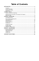
INTRODUCTION Foreword Contact Information We are proud to offer the Grizzly Model H7790/H7791 Laminate Trim Router. These models are part of a growing Grizzly family of fine power tools. When used according to the guidelines set forth in this manual, you can expect years of trouble-free, enjoyable operation and proof of Grizzly’s commitment to customer satisfaction.
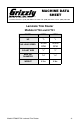
Machine Data Sheet MACHINE DATA SHEET Customer Service #: (570) 546-9663 • To Order Call: (800) 523-4777 • Fax #: (800) 438-5901 Laminate Trim Router Models H7790 and H7791 MODEL HP NO LOAD SPEED COLLET SIZE H7790 ⁄8 5 30,000 RPM ⁄4" 1 H7791 ⁄2 1 30,000 RPM ⁄4" 1 MAX. BIT DIAMETER 11⁄8" 11⁄8" WEIGHT 4 lbs. 4 lbs.
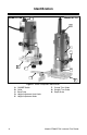
Identification Model H7790 Model H7791 A A D H E B C D F B G C Figure 1. Router component identification. A. B. C. D. E. -4- ON/OFF Switch Collet Base Plate Height Adjustment Lock Knob Height Adjustment Knob F. Curved Trim Guide G. Straight Trim Guide H.
SECTION 1: SAFETY For Your Own Safety Read Instruction Manual Before Operating This Equipment The purpose of safety symbols is to attract your attention to possible hazardous conditions. This manual uses a series of symbols and signal words which are intended to convey the level of importance of the safety messages. The progression of symbols is described below. Remember that safety messages by themselves do not eliminate danger and are not a substitute for proper accident prevention measures.
7. ONLY ALLOW TRAINED AND PROPERLY SUPERVISED PERSONNEL TO OPERATE MACHINERY. Make sure operation instructions are safe and clearly understood. 8. KEEP CHILDREN AND VISITORS AWAY. Keep all children and visitors a safe distance from the work area. 9. MAKE WORKSHOP CHILD PROOF. Use padlocks, master switches, and remove switch keys. 10. NEVER LEAVE WHEN MACHINE IS RUNNING. Turn power OFF and allow all moving parts to come to a complete stop before leaving machine unattended. 11.
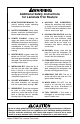
Additional Safety Instructions for Laminate Trim Routers 1. READ THE ENTIRE MANUAL: This manual contains proper operating instructions for this router. 2. SAFETY EQUIPMENT: Wear safety glasses, respirator, and hearing protection when operating a router. 3. POWER SOURCE: Unplug the router and make sure the switch is OFF before inserting or removing bit, making adjustments, or performing maintenance or service. DO NOT make adjustments while the router is running. 4.
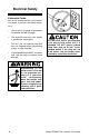
Electrical Safety Extension Cords We do not recommend the use of extension cords, if you find it absolutely necessary: • Use at least a 16 gauge cord that does not exceed 100 feet in length! • The extension cord must also contain a ground wire and plug pin. • DO NOT use an extension cord that has cuts, exposed wires, bent/missing prongs, or other damage. • A qualified electrician MUST size cords over 100 feet long to prevent motor damage.
SECTION 2: OPERATIONS Unpacking/Inventory The Model H7790/H7791 was carefully packed when it left our warehouse. If you discover the tool is damaged after you have signed for delivery, please immediately call Customer Service at (570) 5469663 for advice. Save the box and all packing materials for possible inspection by the carrier or its agent. Otherwise, filing a freight claim can be difficult. When you are completely satisfied with the condition of your shipment, you should inventory the contents.
Adjusting Bit Depth Unplug the router and make sure the switch is OFF before inserting or removing bit, making adjustments, or performing maintenance or service. DO NOT make adjustments while the router is running. To adjust the bit depth: 1. UNPLUG THE ROUTER AND MAKE SURE THE SWITCH IS OFF! 2. Loosen the lock knob shown in Figure 4 and adjust the base to approximately the desired height.
Routing Operations Once the router bit is installed, the depth is set, and the feed direction is determined, it is time to start routing. Routing Tips • Performing routing operations in multiple passes produces smoother results with less chance of “chip out” and burning of the workpiece. It also reduces the possibility of the router jerking out of your hands from trying to remove too much material in one pass. • Cutting end grain with the router will cause tearout.
Curved Trim Guide Straight Guide The curved trim guide is used for trimming curved surfaces, such as adding a decorative edge to a round table or trimming curved corners on a laminate countertop. The straight guide can be used for trimming, cutting dadoes, straight dovetails, and for cutting circles. This guide is only necessary with router bits that do not have a guide bearing. The bushing in the curved trim guide rides along the edge of the workpiece guiding the router bit.
To use the straight guide for interior cuts. To use the straight guide for cutting circles. 1. Set up the straight guide as explained for trimming, but adjust the guide to allow the router bit to follow an interior slot. 1. Set up the straight guide as shown in Figure 9 with the guide plate facing up. Note: When cutting interior slots, the router will tend to wander toward the guide. Keep a constant pressure towards the workpiece, and pull the router towards you, instead of pushing the router.
Template Guide The template guide allows the router to follow a template or pattern. This setup is necessary when routing interior slots where a bit with a guide bearing will not fit. To install the template guide: 1. Remove the screws securing the bottom of the router base as shown in Figure 10. Guidelines for building the template: 1. MDF is the most common template material, but the template can be made out of any material that is flat on the top and bottom, and is at least 3⁄16" thick. 2.
SECTION 3: ACCESSORIES G7984—Face Shield H1298—Dust Sealed Safety Glasses H1300—UV Blocking, Clear Safety Glasses H2347—Uvex® Spitfire Safety Glasses H0736—Shop Fox® Safety Glasses Safety Glasses are essential to every shop. If you already have a pair, buy extras for visitors or employees. You can't be too careful when it comes to shop safety! H1300 H5554—20 Pc. Carbide 1 ⁄4" Router Bit Set H3168—30 Pc.
G1530—Router Pad This natural rubber pad eliminates holding or clamping work while routing or sanding. It effectively grips the workpiece for safe non-slip routing. Thin pad can be easily rolled up and stored when not in use. Pad measures 1⁄ 8" x 24" x 36" Figure 18. G1530 router pad. G3468—Step Gauge Use this solid brass router gauge to set consistent router bit depth. Measures in 1 ⁄ 16" increments. Also includes decimal equivalents. Made in USA.
SECTION 4: MAINTENANCE Router Maintenance Always disconnect power to the machine before performing maintenance. Failure to do this may result in serious personal injury. Router maintenance is simple. Keep the router free from dust, dirt and grease and always store it in a dry place. Plastic parts can easily be cleaned with a damp cloth, but never use water to clean any electrical parts. Solvents should also be avoided on plastic because of the possibility of damage.
H7790 Parts REF 1 2 4 5 6 7 8 9 10 11 12 13 14 15 16 17 18 19 -18- PART # PWRCRD110L PH7790002 PH7790004 P627 PSS23M PH7790007 PH7790008 PH7790009 PS02M PH7790011 PS85M PH7790013 PH7790014 PH7790015 P6200 PH7790017 PH7790018 PH7790019 DESCRIPTION POWER CORD 110V, W/PLUG STRAIN RELIEF BACK COVER BALL BEARING 627ZZ SET SCREW M4-.7 X 10 BRUSH COVER CARBON BRUSH BRUSH TUBE PHLP HD SCR M4-.7 X 12 STATOR PHLP HD SCR M4-.
H7791 Parts REF 1 2 3 4 5 6 7 8 9 10 11 12 13 14 15 16 17 18 19 20 PART # PH7791001 PH7791002 PH7791003 PH7791004 PS56M P627 PH7791007 PH7791008 PH7791009 PH7791010 PH7791011 PH7791012 PH7791013 PH7791014 PH7791015 PH7791016 PH7790017 PH7790018 PH7790019 PFH19M DESCRIPTION POWER CABLE CABLE JACKET BACK COVER CABLE CLAMP PHLP HD SCR M4-.7 X 16 BALL BEARING 627ZZ BEARING GASKET BRUSH TUBE BRUSH COVER CARBON BRUSH MID COVER SHELL STATOR PHLP HD SCR M4-.
WARRANTY AND RETURNS Grizzly Industrial, Inc. warrants every product it sells for a period of 1 year to the original purchaser from the date of purchase. This warranty does not apply to defects due directly or indirectly to misuse, abuse, negligence, accidents, repairs or alterations or lack of maintenance.
WARRANTY CARD Name _________________________________________________________________ Street _________________________________________________________________ City _______________________ State _________________________ Zip _________ Phone # ____________________ Email ________________________ Invoice # _____ Model # ____________________ Order # _______________________ Serial # ______ The following information is given on a voluntary basis.
Send a Grizzly Catalog to a friend: Name________________________________ Street________________________________ City______________State______Zip_______ FOLD ALONG DOTTED LINE Place Stamp Here GRIZZLY INDUSTRIAL, INC. P.O.