MODEL T10010 WET GRINDER COPYRIGHT © NOVEMBER, 2007 BY GRIZZLY INDUSTRIAL, INC. WARNING: NO PORTION OF THIS MANUAL MAY BE REPRODUCED IN ANY SHAPE OR FORM WITHOUT THE WRITTEN APPROVAL OF GRIZZLY INDUSTRIAL, INC.
����������������������������������������������������������������������� �������������������������������������������������������������� ���������������������������������������������������������������������� �������������������������������������������������������������������� ������������������������ ������������������������������������������������������������������ �������������������������������������������������������������������� ����������������������������������������������������������������� ����������
SAFETY For Your Own Safety Read Instruction Manual Before Operating This Equipment The purpose of safety symbols is to attract your attention to possible hazardous conditions. This manual uses a series of symbols and signal words which are intended to convey the level of importance of the safety messages. The progression of symbols is described below. Remember that safety messages by themselves do not eliminate danger and are not a substitute for proper accident prevention measures.
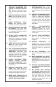
7. ONLY ALLOW TRAINED AND PROPERLY SUPERVISED PERSONNEL TO OPERATE MACHINERY. Make sure operation instructions are safe and clearly understood. 8. KEEP CHILDREN AND VISITORS AWAY. Keep all children and visitors a safe distance from the work area. 9. MAKE WORKSHOP CHILD PROOF. Use padlocks, master switches, and remove switch keys. 10. NEVER LEAVE WHEN MACHINE IS RUNNING. Turn power OFF and allow all moving parts to come to a complete stop before leaving machine unattended. 11.
Additional Safety Instructions for Grinders 1. EYE PROTECTION. Grinding causes small particles to become airborne at a high rate of speed. ALWAYS wear safety glasses when using this machine. 2. WHEEL SPEED RATING. Wheels operated at a faster speed than rated for may break or fly apart. Before mounting a new wheel, be sure the wheel RPM rating is equal to or higher than the speed of the grinder. 4. WHEEL FLANGES. Only use the flanges included with the grinder when mounting wheels.
INTRODUCTION Foreword Contact Info We are proud to offer the Grizzly Model T10010 Wet Grinder. This model is part of a growing Grizzly family of fine power tools. When used according to the guidelines set forth in this manual, you can expect years of trouble-free, enjoyable operation and proof of Grizzly’s commitment to customer satisfaction. Most importantly, we stand behind our tools. If you have any service questions or parts requests, please call or write us at the location listed below.
������������� ����� Customer Service #: (570) 546-9663 • To Order Call: (800) 523-4777 • Fax #: (800) 438-5901 ������������ ����������� ������������������� ������������������������������������������������������������������������������������������������������������� ��� ������������������������������������������������������������������������������������������������������������� ��� ������������������������������������������������������������������������������������������������������������� ��� �������������
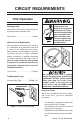
CIRCUIT REQUIREMENTS 110V Operation Electrocution or fire could result if this machine is not grounded correctly or if your electrical configuration does not comply with local and state codes. Ensure compliance by checking with a qualified electrician! Amperage Draw The Model T10010 motor draws the following amps under maximum load: Motor Draw.......................................
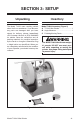
SECTION 3: SETUP Unpacking Inventory The Model T10010 was carefully packed when it left our warehouse. If you discover any parts are damaged after you have signed for delivery, please immediately call Customer Service at (570) 546-9663 for advice. Save the containers and all packing materials for possible inspection by the carrier or its agent. Otherwise, filing a freight claim can be difficult. When you are completely satisfied with the condition of your shipment, you should inventory the contents.
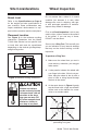
Site Considerations Bench Load Refer to the Specifications on Page 6 for the weight and size specifications of your machine. Some workbenches may require additional reinforcement to support both the machine and the workpiece. Placement Location See Figure 3 for the minimum working clearances. Remember that the Model T10010 Wet Grinder has no specific front or back side and must be repositioned depending on the desired grinding/sharpening/honing action.
4. An undamaged wheel will emit a clear metallic ring or “ping” sound in each of these spots. A damaged wheel will respond with a dull thud that has no clear tone. To test run the machine: 5. If you determine from the ring test that the wheel is damaged, DO NOT use it! 2. Make sure all tools and objects used during set up are cleared away from the grinder. Finally, check that the grinding surface is square. Lower the universal support to 1 ⁄ 16"-1⁄ 8" above the grinding wheel.
OPERATIONS Operation Safety Although the Model T10010 Wet Grinder wheels are designed specifically for slow rotation, there is still the possibility that blades and tools being sharpened on either wheel could be dislodged from your grasp. Be sure that satisfactory space is allocated between the grinder and areas where others are working. Always wear safety glasses and keep the universal support in the proper position when grinding or sharpening.
Positioning the Universal Support The Model T10010 Wet Grinder is equipped with a universal support that serves as a tool rest and as an attachment point for job-specific accessories. It can be attached in two positions, allowing for grinding with or against the rotation direction of the grinding wheel. The tightening knobs on each attachment point allow the universal support to be adjusted and locked in position, depending on the specific task required.
Water Reservoir The Model T10010 Wet Grinder is designed for wet grinding and should never be used without water. Before filling the water reservoir, identify the high and low reservoir mounting slots. These slots allow the reservoir to be raised during grinding and lowered when not in use. The mounting tabs on the reservoir serve as hooks to attach to the reservoir mounting slots (Figure 8). Mounting Tab Upper Slot (Grinding) To fill and position the reservoir: 1.
To use the angle guide: DO NOT allow the grinding wheel to stay immersed in water for long periods of time without running. The water can cause the wheel to become waterlogged and unbalanced and may cause sections of the wheel to break off when the grinder is started. Always empty or lower the reservoir to the storage position when the grinder will not be used.
Wheel Dressing Sharpening Depending on the type of grinding you do, the grinding wheel may require periodic dressing. The leather stropping wheel on the Model T10010 and the included abrasive stropping paste can be used to obtain a razor sharp edge on many tools. Before use, the stropping wheel must be properly prepared. A variety of dressing tools are available (see Accessories, Page 17) and can be used to restore the abrasive quality of the wheel surface and bring the wheel edge back to a square form.
SECTION 5: ACCESSORIES T10023—Accessory Kit #1 Includes fixtures for sharpening small knives, large knives, scissors and axes. T10025—Sharpening Jig. Jig for sharpening 16" planer blades sharpens all planer and jointer blades up to 16" long. Figure 14. Model T10023 T10024—Accessory Kit #2 Includes a stone dresser and fixtures for sharpening scrapers, screwdrivers and hollow chisels. Figure 16. Model T10025. G7120—Heavy Duty Grinder Stand This is one of the most stable bench grinder stands on the market.
H5891, H5892 Diamond Dressers Industrial diamond for dressing grinding wheels. 8¼" long round body with knurled grip for maximum control. Includes protective rubber end cap. Model H5891 ¼ Carat. Model H5892 ¾ Carat. H5944, H5945, H5946 Wheel Dressers Exposes new grains for aggressive cutting on all types of grinding wheels. Star wheels and discs are hardened steel. Cast iron handle provides stabilizing mass for better control. H5944 #0 Wheel Dresser. H5945 #1 Wheel Dresser. H5946 #2 Wheel Dresser.
SECTION 6: MAINTENANCE ! Always DISCONNECT POWER before servicing, adjusting, or doing maintenance to reduce the risk of accidental injury or electrocution. For optimum performance from your machine, routinely check the condition of the following items and repair or replace as necessary: • • • • • • Cracked or loose grinding wheel. Loose hardware. Bent universal support. Worn switch. Worn or damaged cords and plugs. Any other condition that could hamper the safe operation of this machine.
SECTION 7: SERVICE Troubleshooting Motor and Electrical Symptom Possible Cause Solution Motor will not start; fuses or circuit breakers blow 1. Disabling key is at fault. 1. Install/replace disabling key; replace switch. 2. Inspect/repair all lead connections on motor for loose or open connections. 3. Replace start capacitor. 4. Inspect all connections on motor for loose or shorted terminals or worn insulation. 5. Install correct fuses or circuit breakers. 2.
Grinder Operations Symptom Possible Cause Solution Lines on surface of workpiece. 1. Impurity on wheel surface. 2. Workpiece not being held tightly. 1. Dress the grinding wheel. 2. Use a holding device to firmly retain the workpiece. Wheel dulls quickly, grit falls off. 1. Depth of cut too great. 1. Decrease the pressure of the workpiece into wheel. 2. Dress the wheel. 3. Consult manufacturer of grinding wheel. Wavy condition on surface of workpiece. 1. Machine vibrating. Grinding wheel clogs.
Wiring Diagram ��������������������������� ���������������� ��� ��� ����� ��� ������������� �������������������� ����� ������� ����� ������ ��������� �� RED ����� ��������� ����� ������ �� BLUE �� BROWN �� �� ����� �� �� �� �� �� �� ������ Figure 20. Switch connections. -22- Figure 21. Motor connections.
Main Breakdown & Parts List �� � �� �� � � � � �� �� �� �� � �� � �� � � �� �� � �� �� �� �� � � �� �� �� �� �� �� �� �� �� �� �� �� �� �� �� �� ���� ���� �� �� REF PART # DESCRIPTION REF PART # DESCRIPTION 1 2 3 4 5 6 7 8 9 10 11 12 13 14 15 16 17 18 19 20 ANGLE GUIDE HONING PASTE UNIVERSAL SUPPORT HEX NUT M12-1.75 FLAT WASHER 12MM GRINDING WHEEL BUSHING 15MM ID/17MM OD HORIZ. SUPPORT HOLDER VERT.
Warning Labels Breakdown & Parts List 101 102 103 104 REF PART # DESCRIPTION REF PART # DESCRIPTION 101 102 ROTATION DIRECTION ARROW MACHINE ID LABEL 103 104 RESPIRATOR LABEL VERT READ MANUAL-VERTICAL NS 7/05 -24- PT10010101 PT10010102 PT10010103 PLABEL-12A Model T10010 Wet Grinder
WARRANTY CARD Name _________________________________________________________________ Street _________________________________________________________________ City _______________________ State _________________________ Zip _________ Phone # ____________________ Email ________________________ Invoice # _____ Model # ____________________ Order # _______________________ Serial # ______ The following information is given on a voluntary basis.
Send a Grizzly Catalog to a friend: Name________________________________ Street________________________________ City______________State______Zip_______ FOLD ALONG DOTTED LINE Place Stamp Here GRIZZLY INDUSTRIAL, INC. P.O.
WARRANTY Grizzly Industrial, Inc. warrants every product it sells for a period of 1 year to the original purchaser from the date of purchase. This warranty does not apply to defects due directly or indirectly to misuse, abuse, negligence, accidents, repairs or alterations or lack of maintenance.
����������������������������������������������������������������������� ������������������������������������� ������������������������������������ ����������������� �������������������������������� ��������������������������������� ���� ��������������������� ������������������