MODEL T23084 5" PNEUMATIC ANGLE GRINDER INSTRUCTION MANUAL Copyright © DECEMBER, 2010 By Grizzly Industrial, Inc. Warning: No portion of this manual may be reproduced in any shape or form without the written approval of Grizzly Industrial, inc.
This manual provides critical safety instructions on the proper setup, operation, maintenance, and service of this machine/tool. Save this document, refer to it often, and use it to instruct other operators. Failure to read, understand and follow the instructions in this manual may result in fire or serious personal injury—including amputation, electrocution, or death. The owner of this machine/tool is solely responsible for its safe use.
SAFETY For Your Own Safety Read Instruction Manual Before Operating This Equipment The purpose of safety symbols is to attract your attention to possible hazardous conditions. This manual uses a series of symbols and signal words which are intended to convey the level of importance of the safety messages. The progression of symbols is described below. Remember that safety messages by themselves do not eliminate danger and are not a substitute for proper accident prevention measures.
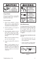
7. AVOID ENTANGLEMENTS. Do not wear loose clothing, gloves, neckties, rings, bracelets, or other jewelry, which may get caught in moving parts, when operating this tool. Wear a protective hair covering to contain long hair. 8. USE CORRECT AIR PRESSURE. Exceeding the maximum PSI rating of this tool may cause unpredictable operation or bursting. 9. DISCONNECT AIR PRESSURE before servicing, changing accessories, or moving to another location. Never leave this tool unattended when connected to air. 10.
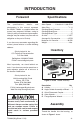
INTRODUCTION Foreword Specifications The specifications, details, and photographs in this manual represent the Model T23084 as supplied when the manual was prepared. However, owing to Grizzly’s policy of continuous improvement, changes may be made at any time with no obligation on the part of Grizzly. Arbor Speed.......... Variable 0–11,000 RPM Arbor Size........................................... 5⁄8"-11 Grinding Wheel Diameter......................... 5" Grinding Wheel Bore.............................
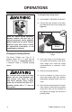
OPERATIONS To change the grinding wheel: 1. DISCONNECT GRINDER FROM AIR! 2. Position the arbor wrench on the arbor flats behind the inner arbor flange (see Figure 2). Arbor Wrench Read the manual before operation. Become familiar with this tool, its safety instructions, and its operation before beginning any work. Serious personal injury may result if safety or operational information is not understood or followed.
EYE INJURY HAZARD! Wear protective equipment when using this tool. LUNG/EAR INJURY HAZARD! Wear protective equipment when using this tool. ACCIDENTAL START HAZARD! Disconnect before service or tool changes. Using Grinder Always test the grinder on a scrap piece of material similar to the workpiece to determine the ideal setup. AIR PRESSURE HAZARD! Never exceed max PSI rating for tool. To use the grinder: 1.
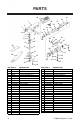
PARTS 44 22 28 1 49 3 23 2 22 21 4 7 8 46 6 27 25 24 26 5 9 11 10 12 13 35 36 20 34 33 37 47 32 30 43 14 45 16 39 15 19 48 31 29 17 41 38 40 42 18 REF PART # DESCRIPTION REF PART # DESCRIPTION 1 2 3 4 5 6 7 8 9 10 11 12 13 14 15 16 17 18 19 20 21 22 23 24 25 MAIN HOUSING PHLP HD SCR M3-.5 X 8 AIR OUTLET PLATE PHLP HD SCR M6-1 X 10 HANDLE O-RING 12.5MM BALL BEARING 626ZZ INT RETAINING RING 10MM O-RING 10MM BEVEL GEAR BALL BEARING 6206ZZ WOODRUFF KEY 12.6 X 3 X 4.