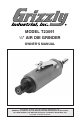
MODEL T23091 1 ⁄4" AIR DIE GRINDER OWNER'S MANUAL Copyright © APRIL, 2011 By Grizzly Industrial, Inc. Warning: No portion of this manual may be reproduced in any shape or form without the written approval of Grizzly Industrial, inc.
This manual provides critical safety instructions on the proper setup, operation, maintenance, and service of this machine/tool. Save this document, refer to it often, and use it to instruct other operators. Failure to read, understand and follow the instructions in this manual may result in fire or serious personal injury—including amputation, electrocution, or death. The owner of this machine/tool is solely responsible for its safe use.
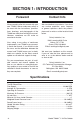
Table of Contents SAFETY.............................................................................................................................2 Safety Instructions for Pneumatic Tools......................................................................2 Additional Safety Instructions for Pneumatic Die Grinders.........................................3 SECTION 1: INTRODUCTION..........................................................................................4 Foreword..........................
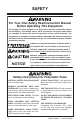
SAFETY For Your Own Safety Read Instruction Manual Before Operating This Equipment The purpose of safety symbols is to attract your attention to possible hazardous conditions. This manual uses a series of symbols and signal words which are intended to convey the level of importance of the safety messages. The progression of symbols is described below. Remember that safety messages by themselves do not eliminate danger and are not a substitute for proper accident prevention measures.
USE PROPER AIR HOSE for the tool. Make sure your air hose is in good condition and is long enough to reach your work without stretching. SECURE WORK. Use clamps or a vise to hold work when practical. It is safer than using your hand and frees both hands to operate tool. MAINTAIN TOOLS WITH CARE. Cracked grinding stones may break and fly apart during operation. Inspect grinding bits for cracks before each use and replace cracked wheels immediately! PREVENT ACCIDENTAL OPERATION.
SECTION 1: INTRODUCTION Foreword Contact Info We are proud to offer this manual with your new T23091! We've made every effort to be exact with the instructions, specifications, drawings, and photographs of the T23091 we used when writing this manual. However, sometimes we still make an occasional mistake. We stand behind our products. If you have any service questions, parts requests or general questions about the product, please call or write us at the location listed below.
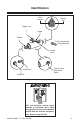
Identification Filter Screen Exhaust Port Trigger Lock Trigger Spindle ⁄ " Quick Disconnect Fitting Removed 14 Throttle Valve Collet Insert Throttle Valve Adjustment Screw Collet Nut Figure 1. Components and controls. This tool presents serious injury hazards to untrained users.
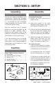
SECTION 2: SETUP Unpacking Assembly Your tool was carefully packaged for safe transportation. Remove the packaging materials from around your tool and inspect it. If you discover the tool is damaged, please immediately call Customer Service at (570) 546-9663 for advice. To assemble the grinder: 1. Remove the plastic plug from the grinder air inlet. Save the containers and all packing materials for possible inspection by the carrier or its agent. Otherwise, filing a freight claim can be difficult.
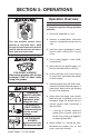
SECTION 3: OPERATIONS Operation Overview To complete a typical cutting or grinding operation: 1. Secure the workpiece in a vise. This tool presents serious injury hazards to untrained users. Read through this entire manual to become familiar with the controls and operations before using the tool! 2. Remove all combustibles, flammable materials, and ignition hazards from the area. 3. Verify the cutter or grinding bit is free of chips or cracks, and install it if it is safe to use. 4.
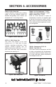
SECTION 4: ACCESSORIES G8210—50-Pc. Stone Set A great selection of high-quality grinding stones in the most common shapes for detailed die-grinding work. Stones are equipped with 1⁄4" mounting shanks. T20881—In-Line Lubricator 1 ⁄4" NPT T20887—Pressure Regulator 1 ⁄4" NPT G6261—Water Filter 1 ⁄4" NPT Install an in-line lubricator to apply oil automatically. Install an air regulator right at the tool for precise air control.
H3105—Clamp Style Magnifying Lamp Mount this lamp to your work table or machine stand for highly detailed viewing. Spring-loaded parallelogram arm design provides full adjustability. Magnifying power is 1.75 times. Great for close-up grinding. Includes two 9 watt bulbs.
SECTION 5: MAINTENANCE ACCIDENTAL START HAZARD! Disconnect before service or tool changes. EYE INJURY HAZARD! Wear safety goggles with full eye protection from all sides when using or servicing this grinder. AIR PRESSURE HAZARD! Never exceed max PSI rating for tool. Daily Maintenance Before and after each use: • Check for leaking or cracked air fittings; bubbled, cut, or worn hoses; and replace as required. • Place a few drops of air tool oil (not motor oil) in the air inlet fitting.
SECTION 6: SERVICE Troubleshooting IMPORTANT: Air tool repairs must be completed by a qualified service person. Symptom Possible Cause Tool runs at normal speed but bogs down when grinding, or tool runs slowly with little air exiting the exhaust. 1. Grinder is being overloaded. Solution 1. Reduce feed pressure; install a new or a smaller diameter bit. 2. Tool adjustment at fault. 2. Re-adjust the throttle valve screw to the fully open position. 3. Trigger or lock is bent and 3.
Symptom Possible Cause Solution Tool does not operate when the trigger is pressed, but air runs freely from exhaust. 1. Motor is at fault. 1. Motor may be stuck in position from improper storage. Lubricate the air tool and rotate spindle by hand a few times. Next use the trigger to operate the air tool while re-oiling several times in the process to flush the tool. Tool runs slowly, 1. Air regulator or tool and only a small adjustment is at fault. amount of air exits from the exhaust port. 2.
SECTION 7: PARTS Main Parts Diagram 7 34 35 33 32 30 3 4 5 6 29 17 16 2 31 22 1 21 27 23 25 24 20 28 26 19 18 27 37 8 9 10 11 12 13 14 15 36 Main Parts List REF PART # DESCRIPTION REF PART # DESCRIPTION 1 2 3 4 5 6 7 9 10 11 12 13 14 15 16 17 18 19 20 21 22 23 24 25 26 27 28 29 30 31 32 33 34 35 36 37 N/A N/A N/A N/A N/A N/A N/A N/A N/A N/A N/A N/A N/A N/A N/A N/A N/A N/A HOUSING THROTTLE VALVE CYLINDER TRIGGER TRIGGER LOCK TORSION SPRING PIN 1.5 X 20MM ROLL PIN 3 X 22MM O-RING 4.8 X 1.
WARRANTY Grizzly Industrial, Inc. warrants every product it sells for a period of 1 year to the original purchaser from the date of purchase. This warranty does not apply to defects due directly or indirectly to misuse, abuse, negligence, accidents, repairs or alterations or lack of maintenance.