MODEL G0637/G0638 71/ 2 & 10 HP CYCLONE DUST COLLECTORS OWNER'S MANUAL Model G0637 Model G0638 COPYRIGHT © MARCH, 2007 BY GRIZZLY INDUSTRIAL, INC. WARNING: NO PORTION OF THIS MANUAL MAY BE REPRODUCED IN ANY SHAPE OR FORM WITHOUT THE WRITTEN APPROVAL OF GRIZZLY INDUSTRIAL, INC.
����������������������������������������������������������������������� �������������������������������������������������������������� ���������������������������������������������������������������������� �������������������������������������������������������������������� ������������������������ ������������������������������������������������������������������ �������������������������������������������������������������������� ����������������������������������������������������������������� ����������
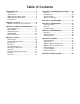
Table of Contents INTRODUCTION ............................................... 2 Foreword ........................................................ 2 Contact Info ................................................... 2 G0637 Machine Data Sheet .......................... 3 G0638 Machine Data Sheet .......................... 5 Identification ................................................... 7 SECTION 1: SAFETY ....................................... 8 Additional Safety for Dust Collectors ...........
INTRODUCTION Foreword Contact Info We are proud to offer the Model G0637/G0638 71⁄2 and 10 HP Cyclone Dust Collectors. These machines are part of a growing Grizzly family of fine woodworking machinery. When used according to the guidelines set forth in this manual, you can expect years of trouble-free, enjoyable operation and proof of Grizzly’s commitment to customer satisfaction.
G0637 Machine Data Sheet G0637 Data Sheet ������������� ����� ������������������������������������������������������������������������������������������ ����������������������������������������� ������������������� � � � ����������������������������������������������������������������������������������������������������������������������������������������������������������������������������� �����������������������������������������������������������������������������������������������������������������
�������������������� � � � � � � � � � � � ������������������������������������������������������������������������������������������������������������������������������������������������ �������� ������������������������������������������������������������������������������������������������������������������������������������������������������ ��������� ���������������������������������������������������������������������������������������������������������������������������������������������������������
G0638 Machine Data Sheet G0638 Data Sheet ������������� ����� ������������������������������������������������������������������������������������������ ���������������������������������������� ������������������� � � � ����������������������������������������������������������������������������������������������������������������������������������������������������������������������������� ������������������������������������������������������������������������������������������������������������������
�������������������� � � � � � � � � � � � ������������������������������������������������������������������������������������������������������������������������������������������������ �������� �������������������������������������������������������������������������������������������������������������������������������������������������������� �������� ��������������������������������������������������������������������������������������������������������������������������������������������������������
Identification A K B J I C D C H F E G Figure 1. Identification (Model G0637 shown). A. Motor —Model G0637: 71⁄2 HP, 220/440V, 3-Phase —Model G0638: 10HP, 220/440V, 3-Phase B. Noise Muffler C. Canister Filter Brush Handles D. Canister Filter E. Collection Bag F. Remote Control G. Collection Drum H. Control Box I. Cyclone Assembly J. Inlet Port K.
����������������� �������������������������������������� ������������������������������������ �������������������������������������������������������������������������������������������������� �������������������������������������������������������������������������������������������� �������������������������������������������������������������������������������������������� �������������������������������������������������������������������������������������������� �������������������� �������������������
��������������������������������� ��� ����� ������ �������� ���� ����� ����� ����������� ���������� ��� �������� ����������� ����� ������ �������������������������������������������� ����������� ��� ��������������������������������� ����� ���� ��������� ���� ��������� �� ����� ���� ������������������������� ���� ����� ��������� ������������ ���� ���������� ������� ���������� ���� ������� ������������������ ���� ������ ������ ����� �������� ��� �������������������������������������� ������� ������ ��� �����
Additional Safety for Dust Collectors 1. MACHINE USE. Do not use this dust collector to pick up liquids and metal scraps, including, but not limited to, nails and filings. Also, do not pick up material which cannot safely pass through the impeller such as solid wood scraps. 2. KEEPING FINGERS SAFE. Do not place your hands or tools near the open inlet during operation. The moving impeller could cause serious damage to body parts if touched while spinning. 3. SAFE SERVICING.
Circuit Requirements SECTION 2: CIRCUIT REQUIREMENTS Serious personal injury could occur if you connect the machine to the power source before you have completed the set up process. DO NOT connect the machine to the power source until instructed to do so. ������� �� ������� Full Load Amperage Draw G0637 71⁄ 2 HP 220V 3-Phase ............... 25 G0637 71⁄ 2 HP 440V 3-Phase ............ 12.5 G0638 10 HP 220V 3-Phase.................30 G0638 10 HP 440V 3-Phase.................
440 conversion Model G0637 440V Conversion The Model G0637 can be rewired for 440V operation. This rewiring job consists of disconnecting the dust collector from the power source, changing the control box, and rewiring the motor. When complete, the rewiring job must be inspected by a qualified electrician before the dust collector is connected to the power source. Refer to the Wiring Diagrams on Pages 45–46 for additional information.
SECTION 3: SETUP Setup Safety This machine presents serious injury hazards to untrained users. Read through this entire manual to become familiar with the controls and operations before starting the machine! Wear safety glasses during the entire set up process! The Model G0637/G0638 is a heavy machine. Serious personal injury may occur if safe moving methods are not used. To be safe, get assistance and use power equipment to move the shipping crate, remove the machine from the crate, and to assemble.
Inventory Inventory After all the parts have been removed from the boxes, you should have the following items: Inventory: (Figures 5–8) Qty A. Upper Stand Braces ................................... 4 B. Upper Stand Legs ...................................... 4 C. Filter Brace Supports (Long) ...................... 2 D. Control Box Bracket ................................... 1 E. Cyclone Mounting Brackets ....................... 4 F. Lower Stand Legs ...................................... 4 G.
Site Considerations Site Considerations L J K Floor Load M N O Figure 6. Model G0637/G0638 inventory J–O. V P Refer to the Machine Data Sheets starting on Page 3 for the weight, footprint, and height specifications of your machine. Some shop floors may require additional reinforcement to support the dust collection system.
Mounting to Shop Floor Mounting to Shop Floor We recommend that you mount your new dust collection system to the floor. Because floor materials may vary, floor mounting hardware is not included. Bolting to Concrete Floors Lag shield anchors with lag bolts and anchor studs (Figure 10) are two popular methods for anchoring an object to a concrete floor. We suggest you research the many options for mounting your machine and choose the one that best fits your specific application.
Hardware Identification Chart G0637/G0638 Cyclone Dust Collector -17-
Assembly 3. Upper Stand 1. Use (8) 3⁄8"-16 x 3⁄4" hex bolts, (16) 3⁄8" flat washers, and (8) 3⁄8"-16 lock nuts to connect 2 upper stand legs, 1 upper stand brace, and 1 lower stand brace —only finger tighten the fasteners (see Figure 12). Use (16) 3⁄8"-16 x 3⁄4" hex bolts, (32) 3⁄8" flat washer, and (16) 3⁄8"-16 lock nuts to connect the two sides of the upper stand with two upper stand braces and two lower stand braces—only finger tighten the fasteners (see Figure 13).
3. When using power lifting equipment during the assembly, make sure the equipment is safe, fully operational, and adequately rated for the weight being lifted. The operator of the equipment must be experienced and able to use safe methods during these processes. Failure to heed these warnings could result in serious personal injury or death. Use the (4) 5⁄16"-18 x 3⁄4" hex bolts and (4) 5⁄16" flat washers to secure the intake cylinder to the bottom of the blower housing (see Figure 16).
4. With assistance, place the intake barrel over the large cyclone funnel and align the mounting holes as illustrated in Figure 17. 6. Install the four cyclone mounting brackets with (8) 5⁄16"-18 x 11⁄4" hex bolts, (16) 5⁄16" flat washers, and (8) 5⁄16"-18 hex nuts (see Figures 17 & 19). ������ ������ �������������� ����� �� ����� ������������� ������ Figure 17. Intake barrel and large cyclone funnel mounting holes aligned.
Note: Orient the two assemblies so that the large, round intake port of the intake barrel is NOT directly underneath the rectangular outlet port of the blower housing. The outlet port will connect to the canister filters and will not allow room for attachment of the intake ducting to the intake port. 4. Mount Blower/Intake Assembly to Upper Stand and Install Lower Stand Legs 1. Attach the two assemblies with the (12) 5⁄16"18 x 3⁄4" hex bolts and (12) 5⁄16" flat washers (see Figure 21).
6. To allow the mounting holes of the lower stand legs to align properly, slightly loosen the 16 fasteners that connect the lower stand braces to the upper stand legs (see Figure 24). Outlet Port and Canister Filters 1. Apply the 3 x 6 x 1100mm gasket to the square side of the outlet port. 2. Mount the outlet port to the blower housing with (4) 5⁄16"-18 x 1" hex bolts, (8) 5⁄16" flat washers, and (4) 5⁄16"-18 hex nuts (see Figure 25).
5. Attach the two long brace supports to the filter braces with (4) 3⁄8"-16 x 3⁄4" hex bolts, (8) 3 ⁄8" flat washers, and (4) 3⁄8"-16 hex nuts, as shown in Figure 27. 7. Assemble the 8" x 311⁄2" flexible ducts, the noise mufflers, and the 8" x 43⁄4" flexible ducts with the 8" duct clamps (see Figure 29). Noise Muffler Flexible Ducts Figure 27. Long brace supports attached. 6.
Small Cyclone Funnel and Funnel Port 1. Dust Collection Drum Assemblies 1. Apply the 3 x 6 x 2200mm gasket to the larger, top end of the small cyclone funnel, then place the cyclone funnel upside down on the floor. For each lower collection drum cylinders, attach the casters to the bottom using (4) 3⁄8"16 hex nuts, (4) 3⁄8" flat washers, and (4) 3⁄8" lock washers (see Figure 32). Note: Use a clean covering on the floor to protect the gasket. 2.
3. Apply the 10 x 50 x 2000mm gaskets to the underside of the collection drum lids (see Figure 34). 6. Figure 34. Applying dust collection drum lid gasket. 4. Install the drum lid latches on the upper part of each collection drum assembly with (12) #10-24 x 3⁄8" Phillips head screws and (12) #10-24 hex nuts (see Figure 35). Attach each set of four bag holder panels with the (24) #10-24 x 3⁄8" Phillips head screws and (24) #10-24 hex nuts to make two dust collection drum bag holders (see Figure 36).
9. Secure the collection drum lids to the collection drums with the lid latches. Model G0638 Control Box 1. 10. Connect the dust collection drum assemblies to the funnel port with the 9" flexible ducts and 9" duct clamps (see Figure 38). Figure 40. Model G0638 control box bracket mounted. Figure 38. Dust collection drum assemblies connected to funnel port. Model G0637 Control Box 1.
Test Run 5. When the assembly is complete, test run your dust collection system to make sure it operates properly. Press the ON/OFF button to turn the machine ON. Make sure your hand stays poised over the switch in case you need to quickly turn the machine OFF. 6. Listen to and watch for abnormal noises or actions. The machine should run smoothly with little or no vibration or rubbing noises.
designing the system SECTION 4: DESIGNING THE SYSTEM General The Model G0637/G0638 is designed to be a central dust collector system. Locate the dust collector in an out of the way location such as a corner or separate room. The large suction capacity of the Model G0637/G0638 allows great flexibility in planning and designing of your dust collection duct layout. Grizzly offers a complete line of dust collection accessories for setting up a stationary system.
There are quite a number of options when it comes to metal duct, but metal duct that is specially manufactured for dust collection is the best choice. When selecting your metal duct, choose high quality metal duct with smooth welded internal seams that will minimize airflow resistance. This type of duct usually connects to other ducts or elbows with a simple, self-sealing clamp, is very quick and easy to assemble, and can be readily dismantled and re-installed.
System Design Step 1. Decide Who Will Design For most small-to-medium sized shops, you can design and build the dust collection system yourself without hiring engineers or consultants. We have included some basic information here to get you started on a dust collection system design. If you have a large shop or must design a complicated system, then we recommend additional research beyond this manual, or seek help from an expert. Step 2.
3. Directional changes should be kept to a minimum. The more directional change fittings you use directly increases the overall resistance to airflow. 4. Gradual directional changes are more efficient than sudden directional changes (i.e. use the largest corner radius possible when changing hose or pipe direction). 5. Each branch line should have a blast gate immediately after the branch to control suction from one machine to another. 6.
Determining Main Line Duct Size The general rule of thumb for a main line duct is that the velocity of the airflow must not fall below 3500 FPM. �� For small/medium sized shops, using the inlet size of the dust collector as the main line duct size will usually keep the air velocity above 3500 FPM and, depending on your system, will allow you to keep multiple branches open at one time. ��� ��� ��� �� �� ��� �� ��� �� �� ��� For the Model G0637/G0638 this is 10". Mark your drawing as in Figure 52.
Calculating Duct Resistance Adding duct work, elbows, branches and any other components to a duct line increases airflow resistance (static pressure loss). This resistance can be minimized by using rigid (smooth) pipe and gradual curves, as opposed to flexible pipe and 90˚ elbows. To help you think about this resistance, imagine riding a bicycle in a tunnel that is an exact replica of your duct work.
Note: When calculating static pressure loss to determine if multiple lines can be left open at the same time, only include the main line numbers once. 5. Compare the total static pressure loss for that line to the maximum static pressure rating of your dust collector (refer to the Machine Data Sheets on Pages 3 & 5). —If your static pressure loss is below the static pressure rating of the dust collector, then the line will most likely be successful.
Always guard against static electrical build up by grounding all dust collection lines. Ensure that the entire system is grounded. If using plastic blast gates to direct air flow, the grounding wire must be jumped (Figure 58) around the blast gate without interruption to the grounding system. External Ground Wire Internal Ground Wire Ground Screw Flex-Hose Figure 59. Flex-hose grounded to machine.
Accessories SECTION 5: ACCESSORIES H5293—4" Metal Duct Starter Kit H5295—5" Metal Duct Starter Kit H5297—6" Metal Duct Starter Kit Save over 20% with this great starter kit. Includes: (2) machine adapters, (10) pipe clamps, (3) 5' straight pipes, (1) branch, (3) pipe hangers, (1) end cap, (3) adjustable nipples, (1) 90˚ elbow, and (1) 60˚ elbow. Figure 60. Metal Duct Starter Kit.
Metal Elbows These industrial metal elbows are available from 4"–8" with 90˚, 60˚, 45˚, or 30˚ curves. Also, available with a 90˚ long radius curve. Call (800) 5234777 or visit www.grizzly.com for more information and pricing. 90° Metal Branches We carry many different branches, all designed to minimize airflow resistance. 90° Long Radius Figure 66. Metal Branches. 30° 45° 60° Reducers & Adapters We carry a multitude of reducers and elbows to cover most applications from 4" through 9". Figure 64.
G6163—4" Clamp G7343—5" Clamp G7361—6" Clamp H5228—7" Clamp H5238—8" Clamp H5253—9" Clamp These clamps feature lever latches and foam seals, and secure around the rolled ends of fittings and pipe. Figure 69. Dust collection pipe clamps. G2752—4" Rolling Floor Sweep G2753—4" Bench Dust Collection Attachment G2754—4" Floor Dust Collection Attachment These attachments are indispensable for collecting dust at machines without a port.
SECTION 6: OPERATIONS Operation Safety Damage to your eyes, lungs, and ears could result from using this machine without proper protective gear. Always wear safety glasses, a respirator, and hearing protection when operating this machine. Do NOT put hands or small objects near inlet openings during operation. Objects sucked into the inlet will meet with the impeller blade. Failure to heed this warning could result in property damage or personal injury.
SECTION 7: MAINTENANCE Cleaning Filters Always disconnect power to the machine before performing maintenance. Failure to do this may result in serious personal injury. Schedule For optimum performance from your machine, follow this maintenance schedule and refer to any specific instructions given in this section. Daily Check: • Dust collector is completely powered down at the end of use. • Dust collection drums and bags. • Loose mounting bolts. • Pressure leaks. • Worn or damaged wires.
Troubleshooting SECTION 8: SERVICE Review the troubleshooting and procedures in this section to fix or adjust your machine if a problem develops. If you need replacement parts or you are unsure of your repair skills, then feel free to call our Technical Support at (570) 546-9663. Troubleshooting Motor & Electrical Symptom Possible Cause Possible Solution 1. Correct short/replace fuse in control box. Machine does not 1. Fuse has blown. start or a breaker 2. Emergency stop push-button is engaged/ 2.
Dust Collector Operation Symptom Possible Cause Possible Solution Loud, repetitious noise, or excessive vibration coming from dust collector. 1. Dust collector is not on a flat surface and wobbles. 2. Impeller is damaged and unbalanced. 1. Stabilize the dust collector. 3. The motor mounting or housing connections are loose. 4. Impeller is loose on the motor shaft. 5. Motor fan cover is dented, causing the motor fan to hit the cover while spinning. 2.
Service Log Date Approximate Hours Of Use G0637/G0638 Cyclone Dust Collector Service Performed -43-
G0637 electrical components G0637 Electrical Components Figure 74. Model G0637 control box. Figure 75. Model G0637 motor wiring (220V).
G0637 control box wiring Wiring Diagrams ����������������� ���������������������� ���������������������������� ������������������������� ������ ��������� ����� �� ����� �� ����� �� ��� �� ��� ����������� �������� ��� �� ������ ����������� ���� ������������� ���� ����������������������������������� ������� ������� ��� ��� �� �� �� �� ���������� ������ ���������������� ��� ��� ������ �������� ��� ��������� ������ ������ ����� ���� ���� ������ ������� �������������������������������� To Moto
G0637 motor wiring ����������� �������������� ����������� ���������������� ��������� �� ����� �� ����� �� ��� �� Control Box (Pages 44 & 45) ������ ����������� �� �� �� �� �� �� �� �� �� �� �� �� �� �� �� �� �� �� �� �� �� �� �� �� �� �� �� �� ���� ����� ��������������������������� �� �� �� �� �� �� �� �� �� �� �� �� �� �� �� �� �� �� �� �� �� �� �� �� �� �� �� �� ���� ������ ���������� When rewiring to 440V, you must purchase and inst
G0638 electrical components G0638 Electrical Components Figure 76. Model G0638 control box. Figure 77. Model G0638 control box cover (shown from back). G0637/G0638 Cyclone Dust Collector Figure 78. Model G0638 motor wiring (220V).
G0638 control wiring ����������������� ���������������������� ��������� ��� ����������� �������� ��� �� ������ ����������� ���� ������������� ���� ����������������������������������� �� �� ���� ���� � ���� �� ���� �� ���� ������ �� ��� �� � �� �� �� � ��� �� �� ���� ���� ���� � ���� � ����� ����� � �� �� ������������������� �� �� � �� � ����� �� �� � � �� ��� ������ �������� ��� ��������� ������ ������ ����� ���� ���� ������ ������� �������������������������������� �
G0638 motor wiring ����������� �������������� ����������� ��������� ����� �� ����� �� ��� �� ������������� Control Box (Pages 47 & 48) ������ ����������� � �� �� �� �� �� �� �� �� �� �� �� �� �� �� �� �� �� �� �� �� �� � �� � When rewiring to 440V, you must purchase and install the 440V Conversion Kit. Refer to Page 12 for details.
Parts Breakdown ���� ���� � ����� ����� ��� ��� �� ��� ��� � � � ����� ��� � ����� ��� ��� ��� ��� ��� ��� � ��� �� �� �� �� �� �� �� ��� �� ��� ��� ��� ��� ��� �� ��� ��� �� �� �� �� �� �� ��� �� ��� �� �� �� � �� �� ��� �� � �� �� �� � �� �� �� �� �� �� ��� ��� ��� �� �� �� �� �� �� �� �� �� �� �� �� �� �� �� �� �� �� �� �� �� �� �� �� �� �� �� �� �� �� �� �� �� �� �� ������ �� �� ��� ��� �� ��� �� ��� ��� ��� �� �� �� �� ���� ���� ���� ���� �� �
Parts List REF PART # 1 P0637001 1 P0638001 1-1 1-2 2 2 3 3 P0637001-1 P0637001-2 P0637002 P0638002 P0637003 P0638003 3-1 P0637003-1 3-1 P0638003-1 3-2 3-2 3-3 P0637003-2 P0638003-2 P0637003-3 3-3 P0638003-3 3-4 P0637003-4 3-4 P0638003-4 3-5 P0638003-5 3-6 P0638003-6 3-7 P0638003-7 3-8 P0638003-8 4 4 5 6 7 8 9 10 11 12 13 14 15 15 16 16 17 17 18 19 20 21 22 23 24 P0637004 P0638004 P0637005 P0637006 PB16 PW02 PLW04 PN08 PB55 PW01 PLW07 PN13 P0637015 P0638015 PW13 P0638016 P063701
Parts List REF PART # DESCRIPTION REF PART # DESCRIPTION 68 69 70 71 72 73 74 74-1 74-2 74-3 74-4 75 76 77 78 79 80 81 82 83 84 85 86 87 88 89 90 91 92 93 94 PW07 PN02 P0637070 P0637071 P0637072 P0637073 P0637074 P0637074-1 PB02 PW06 PN05 PS06 PN07 P0637077 P0637078 P0637079 P0637080 PB04 PN02 P0637083 PS06 PN07 PS06 PN07 P0637088 PW02 PLW04 PN08 P0637092 PB24 PW02 FLAT WASHER 5/16 HEX NUT 5/16-18 HOSE CLAMP 9" FLEXIBLE DUCT 9 x 25-1/2" COLLECTION DRUM LID GASKET 10 X 50 X 2000MM BAG HOLDER RUBBER H
Label Placement 123 126 126 129 122 130 123 131 124 125 128 127 121 132 120 134 133 REF PART # DESCRIPTION REF PART # DESCRIPTION 120 120 121 122 123 124 125 126 127 128 P0637120 P0638120 P0637121 P0637122 PLABEL-14 P0637124 PLABEL-12 P0637126 P0637127 PLABEL-15 MACHINE ID LABEL G0637) MACHINE ID LABEL (G0638) GENERAL WARNINGS LABEL RED HANDLE NOTICE LABEL ELECTRICITY LABEL DISCONNECT POWER LABEL READ MANUAL LABEL HANDS/OUTLET LABEL EYE/LUNG LABEL HEARING HAZARD LABEL 129 129 130 130 131
WARRANTY AND RETURNS Grizzly Industrial, Inc. warrants every product it sells for a period of 1 year to the original purchaser from the date of purchase. This warranty does not apply to defects due directly or indirectly to misuse, abuse, negligence, accidents, repairs or alterations or lack of maintenance.
������������� ���������������������������������������������������������������������������������� � ������������������������������������������������������������������������������������ ����� ����������������������� ������������������������������� ���� ��������������������� ���������������������������� ������ ������������������������ ��������������������������� ���������������������������� ������������������������������� ��������������������������� �������������������������������������������������������������
���������������������� ����� ����� ���� ������������������������ ������������� �������������������������� ���������������������� ����������������������������������� ����������������������������������� ������������������������������������� �������������������������������������� ��������������������������������������
����������������������������������������������������������������������� ������������������������������������� ������������������������������������ ����������������� �������������������������������� ��������������������������������� ���� ��������������������� ������������������