SOMERSET DESIGN + ENGINEERING GROHE GERMANY 96.202.031/ÄM 228507/09.13 www.grohe.com 19 320 D .....1 GB F E I .....2 NL .....6 S .....7 .....3 DK .....8 .....4 .....5 N .....9 FIN ...10 PL .....11 .....16 BG .....21 CN .....26 UAE .....12 TR .....17 EST .....22 UA .....27 GR .....13 SK .....18 LV .....23 RUS .....28 CZ .....14 SLO .....19 LT .....24 H P .....15 HR .....20 RO .....
Please pass these instructions on to the end user of the fitting! S.v.
II 2
1 C A B A1 2 3 2. H 1.
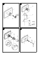
English Installation Mounting escutcheon, see Figs. [4] and [5]. 1. Remove the two screws (A1) and the adaptor (B) from the fitting template (A), then remove the template, see Fig. [1]. 1. Push sleeve (J) with the mark (J1) upward onto the mixer shank, make sure that the marking point (G1) snaps into the sleeve (J), see Fig. [4]. 2. Make sure the water supply is turned on at the service stop valves (C). Stop valves must be in fully open position (slots horizontal) for valve to function. 3.
7 D L D 100 °F (38 °C) 8 9 J M N M1 J1 5 2mm O
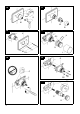
English Adjustment Temperature setting, see Figs. [6] to [9]. • Before the mixer is put into service, if the mixed water temperature measured at the point of discharge varies from the specified temperature set on the thermostat handle. • After any maintenance operation on the thermoelement. 1. Push on adaptor (D) and grease O-ring, see Fig. [6]. 2. Open volume control (L) and measure the temperature of the water emerging with a thermometer, see Fig. [7]. 3.
10 11 2mm O M M N 12 13 K K H G2 G K1 K1 K2 K3 J 14 15 Q C Q2 16 Q1 S1 S R 34mm 77
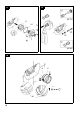
English Maintenance Inspect and clean all parts, replace if necessary and grease with special valve grease. Thermostatic compact cartridge 1. Turn thermostat handle (M) to the 100 °F (38 °C) safety check, see Fig. [10]. 2. Unscrew lever (O). 3. Unscrew cap (N), see Fig. [11]. 4. Pull off thermostat handle (M). 5. Remove caps (K3), screws (K2), snap inserts (K1) and escutcheon (K), see Fig. [12]. 6. Pull sleeve (J) from the mixer shank by pressing down the tongue (G2), see Fig. [13]. 7. Extract clamp (H). 8.
17 18 U U1 T1 V2 V1 T 19 U W 99 X
English Check valves 1. Same procedure as for thermostatic compact cartridge, steps 1-5. 2. Remove the four corner screws (T1) and remove the valve cover (T) as assembled unit with the O-ring (U1), see Fig. [17]. 3. Pull the cartridge holder (U) out of the valve body noting the location of "H" and "C". 4. Remove the check valve inserts (V1) or (V2), see Fig. [18]. If the check valves are removed it is important to reinstall them with the O-ring facing away from the cartridge.
D & +49 571 3989 333 impressum@grohe.de A & +43 1 68060 info-at@grohe.com AUS Argent Sydney & +(02) 8394 5800 Argent Melbourne & +(03) 9682 1231 B & +32 16 230660 info.be@grohe.com BG & +359 2 9719959 grohe-bulgaria@grohe.com CAU & +99 412 497 09 74 info-az@grohe.com CDN & +1 888 6447643 info@grohe.ca CH & +41 448777300 info@grohe.ch CN & +86 21 63758878 CY & +357 22 465200 EST & +372 6616354 grohe@grohe.ee F & +33 1 49972900 marketing-fr@grohe.