
Installation Guide


1
English
Installation
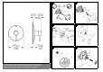
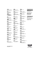
1. Remove the two screws (A1) from the fitting template (A),
then remove the template, see fold-out page I, Fig. [1].
2. Turn the valve stem (B) clockwise to the OFF position.
3. Make sure the water supply is turned on at the service stop
valves (C). Stop valves must be in fully open position (slots
horizontal) for valve to function.
4. The adjustable hot water limit stop (D) is factory set at
neutral position to give maximum outlet temperature, see
Fig. [2] and [5].
Please refer to chapter "Maximum hot water limit setting"
for limiting maximum outlet temperature.
5. Install adapter (E) onto the valve stem (B), by placing the
lever stop pin (E1) on top of the "Arrow" ↑ (F) and tighten
with screw (G), see Fig. [2] and [5].
6. Push cap (H) with drain hole facing down onto the plastic
guide (I) by gently pressing the slotted section (I1) on the
plastic guide, see Fig. [2].
7. Slide the escutcheon mounting base (J) over the cap (H)
and tighten with screws (J1), see Fig. [3].
Do not use excessive force to tighten the screws.
8. Grease seal (K) with the grease provided and slide over
the cap (H).
9. Screw in (clockwise) escutcheon (L) into escutcheon
mounting base (J).
10. Fit lever (M), secure by tightening the loosely fitted set
screw (M1) with 3mm allen wrench and insert plug (M2),
see Fig. [4].
The pressure balancing valve is now ready for use.
Caution!
Do not lift the lever on the handle to operate this valve.
This pressure balancing valve opens from cold to hot by
turning the lever counterclockwise.
If the pressure balancing valve is installed too deep, the
fitting depth can be increased by 1" with an extension set, Part
No. 47 344, see fold-out page II.
Maximum hot water limit setting
The adjustable hot water limit stop (D) is factory set in a
neutral position (0), see Fig. [5].
On applications requiring to limit the valve opening from full hot
position, the factory set adjustable hot water limit stop must be
reset as described below.
1. Remove the factory set adjustable hot water limit stop (D),
see Fig. [6].
2. Slide the adapter (E) onto the valve stem (B), by placing
the lever stop pin (E1) on top of "Arrow" ↑ (F), see Fig. [5]
and fold-out page III, Fig. [7].
3. Turn the adapter (E) counterclockwise until the outlet water
reaches the desired temperature and read the corres-
ponding number (1 to 10, see Fig. [5]) against the lever stop
pin (E1).
4. Close the valve by turning the adapter (E) clockwise and
remove the adapter (E), see Fig. [7].
5. Align the white mark (D1) on the limit stop against the
number (1 to 10, see Fig. [5]) you have selected on the dial
and slide the limit stop (D), see Fig. [8].
6. Proceed to item 5 in chapter Installation.
Note:
The preset maximum temperature will change if the inlet
temperatures change or the setting of the water heater
thermostat is altered.
Winterizing the system
It is recommended that the "pressure balancing cartridge"
be removed from the valve casting if the system is to be shut
off during the winter.
Maintenance
Check, clean and if necessary, replace parts. Grease with
special valve grease.
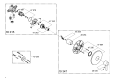
Pressure balancing cartridge, see fold-out page III, Figs. [9]
to [13].
1. Lever out plug (M2) and loosen set screw (M1) with a 3mm
allen wrench, see Fig. [9].
2. Pull off lever (M).
3. Spin escutcheon (L) counterclockwise 1/8 turn and remove,
screw out screws (J1) and pull off mounting base (J).
4. Shut off hot and cold water stops (C). The slots are vertical
when the stops are in the off position, see Fig. [10].
5. Pull off cap (H), loosen screws (I2) and detach plastic
guide (I), see Fig. [11].
6. Close the valve by turning the stem clockwise. Detach stop
ring (N) and note position.
7. Loosen the four corner screws (O1) and remove valve
cover (O).
8. Pull the pressure balancing cartridge (P) out of the valve
body noting the location of "H" and "C", see Fig. [12].
9. Remove the check valve inserts (R), see Fig. [13].
If the check valves are removed it is important to reinstall them
with the O-ring facing away from the cartridge. If they are
installed incorrectly no water will flow.
The pressure balancing cartridge (P) must be replaced as a
complete unit.
Reassemble in reverse order. Ensure that the hot "H" and
cold "C" markings are on the correct side.
Be sure that the stop ring (N) is installed in the position noted
in item 6.
Replacement parts, see fold-out page II (* = special
accessories)
Care
Instructions for care of this faucet will be found in the Limited
Warranty supplement.