
Installation Guide


4
English
Application
Operation is possible in conjunction with:
- Pressurized storage heaters
Operation is not possible with:
- Low-pressure storage heaters
(displacement water heaters)
Technical data
• Max. flow: 5.7 L/min or 1.5 gpm/60 psi
• Flow pressure
- min. 7.25 psi
- recommended 14.5 - 72.5 psi
- greater than 72.5 psi, fit with pressure reducing valves
• Max. operating pressure 145 psi
• Test pressure 232 psi
• Temperature
- max. (hot water inlet) 176 °F
• Water connection cold - Right hand
hot - Left hand
Note
Major pressure differences between cold and hot water supply
should be avoided.
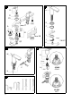
Installation
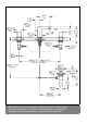
See dimensional drawing on page 1.
Flush piping system prior and after installation of faucet
thoroughly!
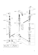
Side valves, see fig. [1].
• Valve with a groove on the top edge of the cartridge (A) and
in addition marked with COLD should be mounted on the
right (cold water) side.
• Valve without a groove on the top edge of the cartridge (A)
and in addition marked HOT should be mounted on the left
(hot water) side.
1. Screw the mounting set (B) to the bottom of the thread of the
side valve (C).
Make sure that the rubber washer (B1) is on the top of the
fiber washer (B2).
2. Insert the side valve (C) through the basin hole from below.
3. Place the escutcheon O-ring (D1) on the basin and screw
down the escutcheon (D) until it stops.
4. Tighten the mounting set (B) from below to secure the valve.
5. Close the cartridges (clockwise for the hot side and counter-
clockwise for the cold side).
Install the lever (E) to the stem of the cartridge (A) and be
sure that the lever points away from the spout.
Spout, see fig. [2] to [4].
1. Place the O-ring (F) and the escutcheon (G) on the basin,
see fig. [2].
2. Insert the spout (H) through the escutcheon (G) and basin.
3. Place the gasket (I) against the bottom of the basin and
fasten with the flange (J) and nut (K). Tighten nut (K) with a
13mm socket wrench.
4. Connect flexible hoses (L) to the side valves, see figs. [3]
and [4].
Mount lift rod and pop-up drain, see fig. [3].
1. Insert the lift rod (M) through the spout and screw on the
lower lift rod (N).
2. The connector is at the lower lift rod (N).
3. Fit pop-up drain (28 957), see page 2.
Ensure that flange of pop-up drain is sealed.
Connect wideset
Connect the side valves to the water supply. Insure the
supplied washers are used for all connections.
The cold water supply should be connected on the right side
valve (marked COLD) and the hot water supply to the left valve
(marked HOT).
Open cold and hot water supply and check connections
for leakage!
Maintenance
Inspect and clean all parts, replace as necessary and grease
with special grease.
Shut off cold and hot water supply.
I. Ceramic cartridge, see fig [5].
1. Remove lever (E).
2. Unscrew the ceramic cartridge (A) using a 17mm wrench.
3. Change complete ceramic cartridge (A) or O-ring (A1).
Observe the different replacement part numbers of the
cartridges.
II. Flow regulator, see page 2.
Unscrew and clean flow regulator (48 159).
Assemble in reverse order.
Replacement parts, see page 2 ( * = special accessories).
Care
Instructions for care of this faucet will be found in the Limited
Warranty supplement.