
Installation Sheet
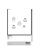


1
English
Application
Operation is possible in conjunction with:
- Pressurized storage heaters
- Thermally controlled instantaneous heaters
- Hydraulically controlled instantaneous heaters
Operation with low-pressure storage heaters (displacement water
heaters) is not possible.
Specifications
• Max. flow 13 L/min or 3.4 gpm/45 psi
• Flow pressure
- min. 7.25 psi
- recommended 14.5 - 72.5 psi
- greater than 72.5 psi, fit with pressure reducing valves
• Max. operating pressure 145 psi
• Test pressure 232 psi
• Temperature
- max. (hot water inlet) 176 °F
• Water connection cold - Right hand
hot - Left hand
Notes
• Installation of backflow protection must comply
with local codes and regulations.
• Major pressure differences between cold and hot water supply
should be avoided.
Installation
See dimensional drawing on fold-out page I.
Flush pipes thoroughly!
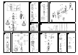
Side valves, see fold-out page II, fig. [1].
• Valve with a groove on the top edge of the cartridge (A) and in
addition marked with blue tape should be mounted on the right
(cold water) side.
• Valve without a groove on the top edge of the cartridge (A) and in
addition marked with red tape should be mounted on the left (hot
water) side.
1. Screw the mounting set (B) to the bottom of the thread of the
side valve (C).
Make sure that the rubber washer (B1) is on the top of the fiber
washer (B2).
2. Insert the side valve (C) through the basin hole from below.
3. Place the escutcheon O-ring (D1) on the basin and screw down
the escutcheon (D) until it stops.
4. Screw the cap (E) down to the escutcheon (D).
5. Tighten the mounting set (B) from below to secure the valve.
6. Close the cartridges (clockwise for the hot side and counter-
clockwise for the cold side).
Mount handle (18 731) or lever (18 732), sold separately,
see fig. [1].
Cross handle (F):
- Secure the handle (F) to the stem of the cartridge (A).
Lever handle (G):
1. Slide ring (G2) on lever (G).
2. Push on lever (G) and tighten with set screw (G1).
3. Screw the ring (G2) into the cap (E) until tight.
Hand tighten only!
It is recommended that the lever (G) be installed so they point away
from the spout when in the off position.
Vacuum breaker, see figs. [2], [3] and [4].
1. Insert the vacuum breaker body with seal (H) and nut (H2)
through the basin hole from below, see fig. [2].
2. Slide on seal (H1) with ring (J) and screw on nut (K).
The distance from the top of the body to the bottom of the ring
must be 2 3/16", see fig. [3].
3. Secure vacuum breaker body to the basin by tightening
nut (H2), see fig. [2].
4. Slide on tube (L) and cover (M), see fig. [4].
5. Tighten the connection tee (N) to the vacuum breaker body with
connection nut (O).
Diverter, see figs. [5] and [6].
1. Insert diverter body with nut (P) and seals (Q), (R1 or R2) and
the lift rod assembly through the basin hole from below,
see fig. [5].
2. Slide on seal (R3 or R4) and screw on nut (S) until it is at the
same height as the top of the diverter body (S1).
3. Secure diverter body to the basin by tightening nut (P) using
an 36mm open-ended spanner.
4. Slide on escutcheon (T), see fig. [6].
5. Mount the diverter knob (U) to lift rod assembly (U1).
Vertical spray, see fig. [7].
1. Insert body with seals (V) from below.
2. Slide on seals (V1) and secure with nut (W) using an 22mm
open-ended spanner.
3. Jet-height can be decreased by turning the nozzle (X) to the left,
turning to the right increases jet-height.
4. Screw on spray face plate (W1).
Fit pop-up drain (28 957), see fold-out page I, ensure that flange
of pop-up drain is sealed.
Connect wideset bidet, see fig. [8] and [9].
1. For this purpose the supply pipes must be installed on to the
angle stops (or other supply points).
2. The cold water supply should be connected on the right, the hot
water supply on the left side.
3. Connect both side valves to the connection tee via the two short
flexible hoses.
4. Connect the vacuum breaker with the blue-marked hose to the
top of the tee and the unmarked hose to the diverter ellbow.
5. Connect the diverter to the vertical spray via the long flexible
hose.
Open cold and hot water supply and check connections for
leakage!
Maintenance
Inspect and clean all parts, replace as necessary and grease with
special grease.
Shut off cold and hot water supply.
I. Ceramic cartridge, see fig. [10].
1a. Loosen handle (F).
1b. Unscrew ring (G2) and remove set screw (G1).
2. Pull off handle (F) or lever (G) and unscrew cap (E).
3. Unscrew the ceramic cartridge (A) using a 17mm wrench.
4. Change complete ceramic cartridge (A) or O-ring (A1).
Observe the different replacement part numbers of the
cartridges, see fold-out page I.
II. Vacuum breaker and check valve, see figs. [8] and [11].
1. Pull off cover (M) and tube (L), see fig. [11].
2. Remove circlip (Y1), pull out and replace double-ball vacuum
breaker (Y).
3. Loosen nut (Z1) using an 21mm open-ended spanner and
replace check valve (Z2), see fig. [8].
III.Vertical spray, see fig. [12].
Unscrew and clean spray face plate (W1) and nozzle (X).
Assemble in reverse order.
Replacement parts, see fold-out page I ( * = special accessories).
Care
Instructions for care of this faucet will be found in the Limited
Warranty supplement.