
Operation Manual


17
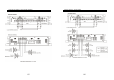
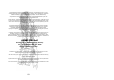
Specifications
Model GZHA 2350XII GZHA 4150XII
GZHA 5125XII
Channel 1-4 Channel 5
RMS Power @ 4 Ω
CEA Standard CEA-2006-A
2 x 260W (1% THD+N)
2 x 320W (10% THD+N)
4 x 130W (1% THD+N)
4 x 160W (10% THD+N)
4 x 100W (1% THD+N)
4 x 120W (10% THD+N)
1 x 270W (1% THD+N)
1x 380W (10% THD+N)
RMS Power @ 2 Ω
CEA Standard CEA-2006-A
2 x 470W (1% THD+N)
2 x 570W (10% THD+N)
4 x 200W (1% THD+N)
4 x 250W (10% THD+N)
4 x 150W (1% THD+N)
4 x 200W (10% THD+N)
1 x 430W (1% THD+N)
1 x 620W (10% THD+N)
RMS Power @ 1 Ω
CEA Standard CEA-2006-A
2 x 740W (1% THD+N)
2 x 900W (10% THD+N)
--- ---
1 x 600W (1% THD+N)
1 x 900W (10% THD+N)
RMS Power @ 4Ω bridged
CEA Standard CEA-2006-A
1 x 940W (1% THD+N)
1 x 1140W (10% THD+N)
2 x 400W (1% THD+N)
2 x 500W (10% THD+N)
2 x 300W (1% THD+N)
2 x 400W (10% THD+N)
---
RMS Power @ 2Ω bridged
CEA Standard CEA-2006-A
1 x 1480W (1% THD+N)
1 x 1800W (10% THD+N)
--- --- ---
Damping factor
> 200 > 130 > 120 > 70
Signal to noise Ratio
> 70 dB > 70 dB > 70 dB
Lowpass
30 Hz – 250 Hz
80 Hz
( Channel 1 & 2 )
30 Hz – 250 Hz
( Channel 3 & 4 )
40 Hz – 3 kHz
( Channel 3 & 4 )
30 Hz – 250 Hz
Highpass
5 Hz – 500 Hz
40 Hz – 3 kHz
( Channel 1 & 2 )
5 Hz – 250 Hz
( Channel 3 & 4 )
40 Hz – 3 kHz
( Channel 1 – 4 )
---
Bandpass
5 Hz – 250 Hz
5 Hz – 250 Hz
( Channel 3 & 4 )
--- 5 Hz – 250 Hz
Subsonic filter
5 Hz – 500 Hz
5 Hz – 250 Hz
( Channel 3 & 4 )
--- 5 Hz – 50 Hz
Bass boost
0 ~ +12 dB --- --- ---
Bass boost frequency
30 Hz ~ 80 Hz --- --- ---
Phase shift
0 – 180°
0 – 180°
( Channel 3 & 4 )
--- 0 – 180°
Frequency response
10 Hz – 38 KHz
(± 1 dB)
10 Hz – 38 KHz
(± 1 dB)
10 Hz – 22 KHz
(± 1 dB)
10 Hz – 250 Hz
(± 1 dB)
Efficiency @ 4 Ω
~ 80 % ~ 80 % ~ 80 %
Input sensitivity
200 mV – 9 V
(± 5%)
200 mV – 9 V
(± 5%)
200 mV – 9 V
(± 5%)
Channel separation
50 dB 50 dB 50 dB
THD
< 0,10 % < 0,10 % < 0,10 %
Bass remote
At lowpass- operation
( Channel 3 & 4 )
---
At lowpass- operation
Fuse
4 x 40A 2 x 40A 3 x 40A
Dimensions
W x H x L mm
305 x 62 x 400 305 x 62 x 400 305 x 62 x 500
Dimensions
W x H x L inch
12 x 2.44 x 15.75“ 12 x 2.44 x 15.75“ 12 x 2.44 x 19.69“
18
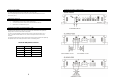
Trouble shooting guide
Symptoms Check Points Cure
No sound
Is the POWER LED illuminated?
Check fuses in amplifier.
Be sure remote lead is connected.
Check signal leads.
Check again control.
Check tuner/deck volume level.
Is the diagnostic LED illuminated?
Check for speaker short or
amplifier overheating
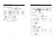
Amp not switching on
No power to the amplifier Check power wire or connections
No power to remote wire with
receiver on
Check connections to radio
No sound in one channel
Check speaker leads
Inspect for short circuit or an open
connection
Check audio leads
Reverse left and right RCA inputs
to determine if it is occurring
before the amp
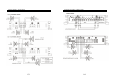
Amp turning off at medium /
high volume
Check speaker loa impedance
Be sure proper speaker load
impedance recommendations are
observed
(If you use an ohm meter to
check speaker resistance, please
remember that DC resistance and
AC impedance may not be the
same.)
Protection LED is on
Temperature shut down Turn radio volume down
Speaker wires short
Separate speaker wires and
insulate