GRUNDFOS INSTRUCTIONS ALPHA 15-55 HWR-D Installation and operating instructions
English (US) Installation and operating instructions . . . . . . . . . . . . . . . . . . . . . . . . . . . . . .
English (US) English (US) Installation and operating instructions Original installation and operating instructions Table of contents 1. Limited warranty. . . . . . . . . . . . . . . 4 2. 2.1 2.2 General information . . . . . . . . . . . . . 4 Hazard statements . . . . . . . . . . . . . . 4 Notes . . . . . . . . . . . . . . . . . . . . . 5 3. 3.1 3.2 Receiving the product. . . . . . . . . . . . 5 Inspecting the product . . . . . . . . . . . . 5 Scope of delivery . . . . . . . . . . . . . . . 5 4. 4.
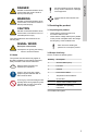
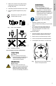
If these instructions are not observed, it may result in malfunction or damage to the equipment. Indicates a hazardous situation which, if not avoided, will result in death or serious personal injury. Tips and advice that make the work easier. WARNING Indicates a hazardous situation which, if not avoided, could result in death or serious personal injury. 3. Receiving the product CAUTION 3.
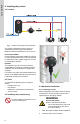
TM073961 4.1 Location Fig. Location of the pump and accessories The system is intended for indoor use only in areas protected from droplets and splashes. Maximum ambient temperature is 104 °F (40 °C). Push-button HWR-D Do not install the push-button HWR-D in a shower or under the tap/faucet where it could be exposed to water. Mount it at a suitable height out of reach of small children and pets.
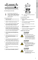
Refer to the arrows on the pump housing indicating the direction of the liquid flow through the pump. 4. Install the pump with horizontal motor shaft. 5. Fit the two gaskets supplied to the pump ends. WARNING Pressurized system Death or serious personal injury ‐ Before dismantling the pump, drain the system or close the isolating valve on either side of the pump before you remove the screws. The pumped liquid may be scalding hot and under high pressure.
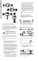
English (US) Then press and hold the connect button on the temperature sensor for more than 2 seconds. The temperature sensor's internal blue LED will flash. After successful pairing of the pump and the temperature sensor, the blue light will be on continuously for 5 seconds on both devices. If the pairing fails, the connect symbol will flash red for 5 seconds on the pump. If pairing fails, retry the pairing procedure. A B C 5. Replace the lid of the temperature sensor case. 6.
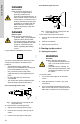
English (US) TM072160 Fig. Double-sided tape Replacing the lid and and the screws 4.4.4 Installing the push-button To install the push-button: 1. Remove the mounting bracket from the back of the push-button. 2. Remove the pull-tab from the end of the AAA batteries. The push-button will start up. 3. Use the included double-sided tape to fasten the mounting bracket to a surface or wall away from water droplets or splashes. 4.
Electric shock Death or serious personal injury ‐ This pump is supplied with a grounding conductor and grounding-type attachment plug. To reduce the risk of electric shock, be certain that it is connected only to a properly grounded, grounding-type receptacle in accordance with the National Electric Code and any state, local governing codes and regulations. 3 1 2 Fig.
2 3 4 5 TM072150 1 English (US) 6.2 Accessories 5.2 Starting the pump Fig. • • Pos. Description 1 "Connect" LED 2 "Temperature sensor" LED 3 "Power ON" LED 4 Pairing button 5 "Pump operation" LED Connect the line cord to the power supply to start the pump. The pump will run for approx. 5 seconds and then stop. The green "Power ON" LED on the pump display will be lit when the power is on. TM072805 • "Power ON" LED and other indicators on the pump display Fig. Pos.
The ALPHA 15-55 HWR-D system is intended for domestic hot-water recirculation. When you activate the system with the HWR-D push-button, the pump starts circulating hot water. To prevent continuous operation, the pump stops recirculating water again when: a) the media temperature measured at the temperature sensor has increased by 10 °F or is higher than 102 °F. or b) the pump has been operating continuously for more than 5 minutes, or for a total of 15 minutes during the last hour.
Approval marks FCC sections Section 15.19 (a) 3 This device complies with Part 15 of the FCC Rules. Operation is subject to the following two conditions: (1) this device may not cause harmful interference, and (2) this device must accept any interference received, including interference that may cause undesired operation. Section 15.21 Any changes or modifications to this equipment not expressly approved by the party responsible for compliance could void the user's authority to operate this equipment.
Pump display symbol 7.1 Pump display Status Explanation the pushbutton or temperature sensor. Flashing red (2 seconds) during normal operation Flashes red for 2 seconds when the battery level in the push-button is at a critical level. Replacement of the batteries in the pushbutton is recommended. Green Lights green for 2 seconds when the push-button is activated during normal operation.
Explanation Flashing red (5 seconds) during installation The LED flashes red for 5 seconds when pairing between the temperature sensor and the pump has failed. Restart of the installation procedure is recommended. English (US) Status 7.3 Push-button LED LED status Explanation Flashing blue The LED flashes blue when the push-button is ready for pairing with the pump. Blue The LED lights blue for 5 seconds when pairing between the push-button and the pump has succeeded.
The pump runs at a constant speed and consequently on a constant curve. The pump is set on the maximum curve under all operating conditions. H [m] 5.5 5.0 4.5 H [ft] ALPHA 15-55 HWR-D 60 Hz 18 17 16 15 14 4.0 3.5 3.0 13 12 11 10 9 2.5 2.0 1.5 8 7 6 Without check valve installed With check valve installed 5 4 1.0 0.5 3 2 1 0.0 0 0 0.0 1 2 0.5 3 4 1.0 5 6 7 1.5 8 9 2.0 10 11 12 13 14 15 16 17 18 Q [US GPM] 2.5 3.0 3.5 Q [m³/h] TM072501 English (US) 7.5 Pump curve Fig.
8.1.1.2 Battery replacement for push-button 8.1 Maintaining the product The ALPHA HWR-D pump is maintenance-free. If the pump is damaged, for example with fractures or dents, replace the pump. The push-button uses AAA 1.5 V alkaline batteries. To change the battery in the push-button, follow these steps: 1. Remove the push-button from the mounting bracket on the back of the push-button. 8.1.1 Battery replacement 2. Remove the old batteries. WARNING 3. Insert the two new batteries.
English (US) 9. Fault finding the product 9.1 Fault finding table Fault: The pump does not start. Status Cause Remedy Make sure the power supply is switched on. "Power On" LED on the pump control panel is not lit. The pump is not connected to the power supply. Check if external protection has tripped. Make sure the cables and connections are free from defects and connected securely. The "Power On" LED on the pump control panel is green. The The pump is in an alarm state. "Pump Operation" LED is red.
English (US) Fault: There is noise in the circulator pump. Status There are no indicators lit on the pump or accessories. Cause Remedy Air is trapped in the pump. Open a faucet or tap to let trapped air escape. No liquid. Ensure there is liquid in the hot water supply source.
English (US) 10. Technical data 10.1 Operating conditions Supply voltage Ambient temp. Min. liquid temp. Max. liquid temp.
GRUNDFOS Pumps Corporation 9300 Loiret Boulevard Lenexa, Kansas 66219 USA Tel.: +1 913 227 3400 Fax: +1 913 227 3500 GRUNDFOS Water Utility Inc. 3905 Enterprise Court P.O. Box 6620 Aurora, IL 60598-0620 Phone: +1-630-236-5500 Fax: +1-630-236-5511 GRUNDFOS CBS Inc. 902 Koomey Road Brookshire, TX 77423 USA Phone: 281-994-2700 Toll Free: 1-800-955-5847 Fax: 1-800-945-4777 Peerless Pump 2005 Dr. Martin Luther King Jr US-46202 Indianapolis, Indiana U.S.A. Phone:317-925-9661 Canada GRUNDFOS Canada Inc.
99475026 ECM: 1251559 Trademarks displayed in this material, including but not limited to Grundfos, the Grundfos logo and “be think innovate” are registered trademarks owned by The Grundfos Group. All rights reserved. 0119 © 2019 Grundfos Holding A/S, all rights reserved.