
TP50-160/2 Shaft Seals Manual
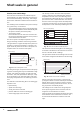
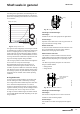
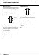
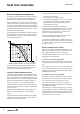
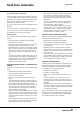
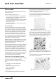
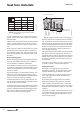
Table Of Contents

12
Shaft seals in general
Shaft seals
Friction, wear and leakage
The seal faces of a shaft seal are lubricated by the
pumped liquid. Thus, better lubrication means less fric-
tion and increased leakage. Conversely, less leakage
means worse lubrication conditions and increased fric-
tion.
The following factors contribute to the power consump-
tion ("power loss") of a shaft seal:
• The centrifugal pumping action of the rotating parts.
The power consumption increases dramatically with
the speed of rotation (to the third power).
• The seal face friction.
Friction between the two seal faces consists of fric-
tion in the thin liquid film and friction due to points of
contact between the seal faces.
The level of power consumption depends on seal
design, lubricating conditions and seal ring materials.
The figure below is a typical example of the power con-
sumption of a shaft seal operating in cold water. The
figure shows the power loss of each of the power con-
sumption factors as a function of the speed.
Fig. 11
Power consumption of seal
According to the figure, the power loss due to the pump-
ing action of rotating parts may be considerable at high
speeds. This applies for example to shaft seals with
seal driver. Thus, with speeds above 6000 rpm, it may
be an advantage to use shaft seals where seal driver
and springs are positioned in the stationary part of the
seal.
The thickness of the lubricating film in the sealing gap
depends on the
• liquid viscosity
• speed of the seal rings
• closing force of the shaft seal
• pressure difference across the sealing gap
• surface topography of the seal faces.
The viscosity of water decreases with temperature,
causing a reduction of the lubricating film. When the
temperature exceeds +100°C, the lubricating condi-
tions deteriorate substantially because a considerable
part of the seal face is steam lubricated. Thus friction
and wear on the seal rings increase with temperature.
To prevent excessive wear, the closing force and differ-
ential pressure can be reduced by balancing the seal.
Fig. 12
Wear rate for different balancing ratios
The thickness of the lubricating film in the sealing gap
is sensitive to the flatness of the seal faces. An uneven-
ness of 0.001 mm results in leakage.
The figure below shows how the leakage rate of a shaft
seal in water changes with the flatness of the seal rings.
Fig. 13
Flatness as a function of leakage
With an unevenness of 0.001 mm, a hard seal ring
(of tungsten carbide or ceramic material) has increased
leakage during a typical running-in period of several
weeks. If the seal ring surface is less uneven, the run-
ning-in period is considerably shorter.
The leakage rate of a shaft seal is also greatly influ-
enced by the roughness of the seal faces; both the
roughness size and direction are critical.
Figure 15 shows how the leakage rate differs according
to the direction of the scratches on the surface. The
arrows indicate the direction of rotation of the seal
rings.
TM02 7452 3603
0
50
100
150
200
250
0 2000 4000 6000 8000 10000 12000
pumping
friction
Power loss [W]
Speed [rpm]
TM02 7110 2603TM02 7453 3603
0 20 40 60 80 100 120 140 [°C]
BUBE K=1.2
HUBE K=1.0
KUBE K=0.8
Wear rate (comparative)
Temperature
0
0.2
0.4
0.6
0.8
1
1.2
1.4
1.6
1.8
0 0.2 0.4 0.6 0.8 1 1.2 1.4
Flatness [micrometer]
Leakage [ml/h]