GRUNDFOS INSTRUCTIONS Grundfos Variable Speed Installation and Operation Pumps Incorporating the (VS) Variable Speed Control with Date Code 0838 or higher 1. 2. 3. 4. Shipment Inspection General Features Operational Limits Pump Installation 5. 6. 7.
Grundfos Variable Speed Pump It has been carefully inspected and tested before shipment. It should give you long, efficient, troublefree service. For maximum performance and reliability, please follow the simple instructions in this manual.
1. Shipment Inspection Check the contents of this package. Care should be taken to ensure the pump is NOT dropped or mishandled; dropping will damage the pump. Grundfos Variable Speed Pump Package Includes: • • • • One Grundfos UP15-42 or UP26 Variable Speed pump with integral control. One 6’ line cord with 115V plug, pre-wired into control box. Two flange gaskets Installation and Operating Instructions. 2. General Features • All minimum and maximum settings are operating, not safety limits.
3. Operational Limits Control Signal Input Range Options: Voltage signal range: 0-10V(DC) or 2-10V(DC) Current signal range: 0-20mA or 4-20mA Grundfos Variable Speed pumps are designed to pump liquids compatible with their cast iron pump housing construction. They are recommended for use in closed hydronic systems. Grundfos Variable Speed pumps are for Indoor Use Only. Grundfos Variable Speed Pumps are intended for use with water, or a 50/50 mixture by weight of propylene glycol.
4. Pump Installation Warning: Consult piping manufactures for material selection before installing this pump. Absence of pumping fluid may damage some piping materials.
The pump must be installed with the motor shaft positioned horizontally. Under no circumstances should the pump be installed with the shaft vertical or where the shaft falls below the horizontal plane (Fig. 1). • Ensure that water does not enter the terminal box during the installation process. • DO NOT START THE PUMP UNTIL THE SYSTEM HAS BEEN FILLED AND CHECKED FOR LEAKS. • Do not use the pump to vent the system. • Never operate the pump dry.
Electrical Connections To The Control: CAUTION: The installer should confirm that no current/voltage is present at any of the wires. Note: Control signal wires must be run through and secured by the stain relief on the terminal board. Note: No speed control signal is necessary if speed is to be regulated using the manual % dial. Current Speed Control Signal Connections: Connect the current signal wires to terminals “Com(-)” and “Ret/I” (Fig 3.).
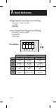
Settings 7. Settings 6. Setting Dip Switches: Switches Setting � Figure Figure 5 - 7A Dip Switches Dip Switches Dip Dip switch Switchsettings Settings: SWITCH A ON POSITION OFF DEFAULT mA (V) DC mA C 2-10V 4-20mA min speed off 0-10V 0-20mA min speed 15% 2-10V 4-20mA min speed off D speed control external speed control manual % dial speed control external B FeatureExplanation Explanation Feature Dip Switch minimum speed speedoff/minimum off/minimum speed Dip switch CC- -minimum speed 15%.
Multi Function Dial On Terminal Box MultiFunction FunctionDial Dial On Terminal Box Multi On Terminal Box: Offset Dial (When dip switch D is on) Offset dipswitch switchDDisison) ON) Offset Dial Dial (When dip The Offset dial allows the user to fine tune the input The the input TheOffset Offsetdial dialallows allowsthe theuser usertotofine finetune tune the input signal. The input signal may be varied plus or minus 1signal. signal.
7. Quick Reference Voltage Speed Control Signal Circuit Rating: Terminals : Com(-) & Os/V 0-10VDC 5mA Max 7. Settings 7.
Grundfos Variable Speed Control Board On Made in Canada Power: 120 ±10% 50/60 Hz 240 VA Demand: 20-30 V (ac) 0.1 VA Var. Speed: 120 V (ac) 1.8 A 1/12 hp Relay: 30 V (ac), 2.5 A pilot duty Off 0.1 ȝF 250V 100µ 100 ȝH 6 A inductor Meets Class B: Canadian ICES Fcc Part 15 R R A B C D MOV 115 V : 18 V Signal wires must be min. 300V rating 0.1µF 1008-02 599395 May 2006 12345 Use copper conductors only Transformer 1 VA Fuse Boil Boil Os / V Ret / I Com(-) Sup Com tN4 Pot tekmar no.
Limited Warranty Products manufactured by GRUNDFOS PUMPS CORPORATION (GRUNDFOS) are warranted to the original user only to be free of defects in material and workmanship for a period of 24 months from date of installation, but not more than 30 months from date of manufacture. GRUNDFOS' liability under this warranty shall be limited to repairing or replacing at GRUNDFOS' option, without charge, F.O.B. GRUNDFOS' factory or authorized service station, any product of GRUNDFOS manufacture.