
Install Instructions


Page 8
Multi Function Dial On Terminal Box
Offset Dial (When dip switch D is on)
The Offset dial allows the user to fine tune the input
signal. The input signal may be varied plus or minus 1-
5%. This offset will affect the signal through it's entire
range. The factory default is 0. The offset setting
cannot increase the output to greater than 100% or less
than the selected minimum output of either 0% or 15%.
Example:
The measured input signal is 2.1-10.1V and as a result
the pump does not shut off because the signal doesn't
drop to 2V. The dial is set to -5%
and the input signal is offset
down to 2.0-9.6V. The pump
will now shut off, however the
pump will not reach the full 10V
speed now, due to the offset.
Manual % Dial (When dip switch D is off)
The manual % dial allows the speed of the pump to be
manually adjusted and set by the user. The speed of
the pump may be manually adjusted anywhere from
min to 100%, but once set remains fixed at that speed.
The "min" position on the dial will either be equal to
"OFF" or "15%" depending on the position of dip switch
C. The factory default is 50%.
Performance Indicator LEDs (Fig. 7c)
Power ON (green) indicates power is applied.
% Out (Yellow) indicates the speed of the pump by
flashing at different rates.
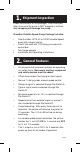
Before You Leave
• Place this brochure, and all other brochures
relating to the installation, in a conspicuous
location near the control for future reference.
• It is important to explain the operation of this
control within the system to the end user and to
anyone else who may be operating the system.
Page 8
Figure 7C - Performance
indicator LEDs
Figure 7B - % Offset
Offset /
Manual %
-5%
0
-1
-2
-3
-4
+1
+2
+3
+4
+5%
Min 100%
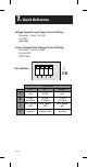
Multi Function Dial On Terminal Box:
Offset Dial (When dip switch D is ON)
The Offset dial allows the user to fine tune the input
signal. The input signal may be varied plus or minus 1-
5%. This offset will affect the signal through it’s entire
range. The factory default is 0. The offset setting
cannot increase the output to greater than 100% or less
than the selected minimum output of either 0% or 15%.
Example:
The measured input signal is 2.1-10.1V and as a result
the pump does not shut off because the signal doesn’t
drop to 2V. The dial is set to -5%
and the input signal is offset
down to 2.0-9.6V. The pump
will now shut off, however the
pump will not reach the full 10V
speed now, due to the offset.
Figure 6 - % Offset
Manual % Dial (When dip switch D is OFF)
The manual % dial allows the speed of the pump to be
manually adjusted and set by the user. The speed of
the pump may be manually adjusted anywhere from
min to 100%, but once set remains fixed at that speed.
The “min” position on the dial will either be equal to
“OFF” or “15%” depending on the position of dip switch
C. The factory default is 50%.
Install control onto the pump. Insert the 115 V plug on
the line cord from the pump into a properly grounded
115 V outlet. This will apply power to the pump/control.
Performance Indicator LEDs (Fig. 7)
Power ON (green) indicates power is applied.
% Out (Yellow) indicates the speed of the pump by
flashing at different rates.
Before You Leave
• Place this brochure, and all other brochures
relating to the installation, in a conspicuous
location near the control for future reference.
• It is important to explain the operation of this
control within the system to the end user and to
anyone else who may be operating the system.
Figure 7 - Performance
indicator LEDs
Multi Function Dial On Terminal Box
Offset Dial (When dip switch D is on)
The Offset dial allows the user to fine tune the input
signal. The input signal may be varied plus or minus 1-
5%. This offset will affect the signal through it's entire
range. The factory default is 0. The offset setting
cannot increase the output to greater than 100% or less
than the selected minimum output of either 0% or 15%.
Example:
The measured input signal is 2.1-10.1V and as a result
the pump does not shut off because the signal doesn't
drop to 2V. The dial is set to -5%
and the input signal is offset
down to 2.0-9.6V. The pump
will now shut off, however the
pump will not reach the full 10V
speed now, due to the offset.
Manual % Dial (When dip switch D is off)
The manual % dial allows the speed of the pump to be
manually adjusted and set by the user. The speed of
the pump may be manually adjusted anywhere from
min to 100%, but once set remains fixed at that speed.
The "min" position on the dial will either be equal to
"OFF" or "15%" depending on the position of dip switch
C. The factory default is 50%.
Performance Indicator LEDs (Fig. 7c)
Power ON (green) indicates power is applied.
% Out (Yellow) indicates the speed of the pump by
flashing at different rates.
Before You Leave
• Place this brochure, and all other brochures
relating to the installation, in a conspicuous
location near the control for future reference.
• It is important to explain the operation of this
control within the system to the end user and to
anyone else who may be operating the system.
Page 8
Figure 7C - Performance
indicator LEDs
Figure 7B - % Offset
Offset /
Manual %
-5%
0
-1
-2
-3
-4
+1
+2
+3
+4
+5%
Min 100%