GRUNDFOS INSTRUCTIONS UPS Series 200 Circulator pumps Installation and operating instructions
(QJOLVK 86 English (US) Installation and operating instructions CONTENTS 1. Limited warranty Page 2 1. Limited warranty 2. 2.1 Introduction Safety warning 3 3 3. 3.1 3.2 3.3 3.4 Pre-installation checklist Confirm you have the correct pump Check the condition of the pump Verify electrical requirements Pumped liquid requirements 3 3 3 3 4 4. 4.1 4.2 4.3 4.4 Installation procedures Electrical preparation Piping considerations Connect the pump Electrical connection 5 5 5 6 6 5. 5.1 5.2 5.
. Pre-installation checklist 2.1 Safety warning 3.1 Confirm you have the correct pump 2.1.1 Read this booklet This booklet is designed to help a certified installer install, begin operation of and troubleshoot the Grundfos UPS pumps. The booklet should be left with the owner of the pump for future reference and information regarding its operation. Should the owner experience any problems with the pump, a certified professional should be contacted. • 2.1.
(QJOLVK 86 3.4 Pumped liquid requirements CAUTION: The UPS pump is intended for use with water only. The pump can be used to circulate: • Potable hot water • Water for hydronic heating • Cooling water • In domestic hot-water systems it is advisable to use bronze pumps (UPS model) only for water with a degree of hardness lower than 14 grains per gallon of hardness. For water with a higher degree of hardness, a direct-coupled Grundfos TP pump is recommended.
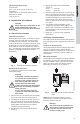
4. Installation procedures Warning Never make any connections in the pump terminal box unless the electrical supply has been switched off. 4.1 Electrical preparation TM03 7296 4706 Terminal box position At the bottom of the stator, closest to the pump housing, there are eight drain holes to allow condensed water to escape. The drain holes shall not be blocked. The drain holes must point downwards. The terminal box must therefore point upwards in one of the positions shown in fig. 1.
4.4.1 UPS 1 x 115 V and 1 x 230 V terminal box 4.4 Electrical connection Protection module The electrical connection and protection should be carried out in accordance with the latest edition of the National Electrical Code, local codes and regulations by a qualified electrician. Warning Never make any connections in the pump terminal box unless the electrical supply has been switched off. The pump must be grounded. The pump must be connected to an external main power switch.
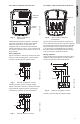
4.4.2 UPS 3 x 208-230 V terminal box Standard module Jumpers L3 P2 P1 Fig. 5 T3 L1 L2 T4 T2 T6 T1 TM03 7739 4806 TM03 7742 4806 T5 Speed switch (QJOLVK 86 4.4.3 UPS 3 x 460 V and 575 V terminal box Fig. 8 UPS 3 x 208-230 V terminal box UPS 3 x 460 V and 575 V terminal box All UPS pumps with three-phase x 208-230 V come with a standard module and a speed switch as shown in fig. 5.
L3 K Start K K L2 L3 Stop P1 T3 T2 L1 T1 P2 Fig. 10 External impulse contacts 5. Starting the pump 5.1 Vent the piping system Applies to 460 V and 575 V two-speed models only (The direction of rotation of three-speed pumps is checked by means of the fault finding chart, p. 10 and p. 11). 1. Make sure that the power is OFF. 2. Unscrew and remove the vent plug located at the center of the nameplate. 3. Insert a small, flat-blade screwdriver into the slot in the end of the motor shaft (see fig.
5.3.1 Three-speed pumps, all models except 3 x 460 V and 575 V The speed switch in the terminal box can be turned to three positions. The speed in the three positions appears in the table below (also see fig. 13). Speed in % of maximum speed Three-phase pumps 1 approx. 60% approx. 70% 2 approx. 80% approx. 85% 3 100% 100% 5.3.2 Two-speed pumps, 3 x 460 V and 575 V The speed setting in the terminal box can be changed to two positions.
(QJOLVK 86 6. Troubleshooting 6.1 Fault finding chart Warning Before removing the terminal box cover, make sure that the electrical supply has been switched off and that it cannot be accidentally switched on. The pumped liquid may be scalding hot and under high pressure. Before any removal or dismantling of the pump, the system must be drained or the isolation valves on both sides of the pump must be closed. Fault Cause Remedy 1. a) One fuse in the installation is blown. Replace the fuse.
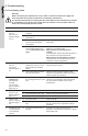
7. Single-phase pumps with protection module (only). The pump does not run. The red indicator light is on. The green indicator light is off. Cause Remedy a) The pump has been cut out by the thermal overload switch due to high liquid temperature or blocked rotor. Check that the liquid temperature falls within the specified range. The pump will restart automatically when it has cooled to normal temperature.
6.4 Insulation resistance (lead-to-ground) check the current, use an ammeter. do so, follow these steps: Make sure the pump is operating. Set the ammeter to the proper scale. Place the tongs of the ammeter around the leg to be measured. 4. Compare the results with the amp draw information on the motor nameplate. 5. Repeat for the other legs.
(QJOLVK 86 6.5 Winding resistance (line-to-line) To check the winding resistance of the motor windings, a megohmmeter is required. To do so, follow these steps: 1. Turn the POWER OFF. 2. Disconnect all electrical leads to the motor. 3. Set the scale selector on the megohmmeter to R x 1, touch its leads together, and adjust the indicator to zero. 4. Using the charts below for reference, touch the leads of the megohmmeter to the appropriate pair of connectors.
(QJOLVK 86 Internal wiring UPS Terminal plug in stator Three-phase 460/575 V 14 1 3 5 13 7 9 11 15
(QJOLVK 86 6.6 Winding resistance chart 60 Hz Pump type UPS 32-40/4 UPS 32-80/2 UPS 32-160/2 UPS 40-40/4 UPS 40-80/2 UPS 40-80/4 UPS 40-160/2 Voltage [: ] 68 ºF - 122 ºF (20 ºC - 50 ºC) R RA RS1 RS2 1 x 115 V 17.8 - 23.2 3.95 - 5.20 9.40 - 12.4 1 x 230 V 70.0 - 91.5 17.0 - 22.2 39.5 - 52.0 1 x 115 V 9.55 - 12.6 3.05 - 4.00 6.70 - 8.80 1 x 230 V 19.4 - 25.5 5.45 - 7.10 12.6 - 16.4 1 x 115 V 4.15 - 5.45 1.20 - 1.56 2.65 - 3.50 1 x 230 V 8.30 - 10.8 2.20 - 2.90 5.05 - 6.
(QJOLVK 86 Pump type UPS 50-40/4 UPS 50-80/2 UPS 50-80/4 Voltage [: ] 68 ºF - 122 ºF (20 ºC - 50 ºC) RA RS1 1 x 115 V 6.55 - 8.55 2.12 - 2.80 4.30 - 5.65 1 x 230 V 25.0 - 33.0 8.30 - 10.8 15.0 - 19.8 1 x 115 V 4.15 - 5.45 1.20 - 1.56 2.65 - 3.50 1 x 230 V 8.30 - 10.80 2.20 - 2.90 5.05 - 6.65 1 x 115 V 2.75 - 3.60 1.74 - 2.30 2.85 - 3.75 1 x 230 V 5.50 - 7.25 2.65 - 3.50 4.95 - 6.50 6.80 - 8.95 2.02 - 2.65 3.70 - 4.85 1 x 115 V 4.15 - 5.45 1.20 - 1.56 2.65 - 3.
(QJOLVK 86 7. Replacing components 7.1 Removing the pump head 1. Disconnect or TURN OFF the power supply. 2. Close any isolation valves on either side of the pump to avoid draining the system of liquid. 3. Disconnect the electrical leads from the terminal box. 4. Disconnect and remove the conduit from the terminal box. 5. Loosen and remove the four allen-head screws (8 or 10 mm) which connect the pump head housing to the pump housing. 6. Remove the pump head from the pump housing. 7.
Frame ground screw hole If the terminal box is replaced, make certain the electrical information listed on the new box matches the information listed on the old box, and that it is compatible with the pump and incoming electrical supply. For all terminal boxes, it is very important to tightly secure the frame grounding screw through the terminal box, so that a proper connection between the terminal box and motor is made. Standard module Speed switch Electrical information Fig.
SOMMAIRE 1. Garantie Limitée 2. 2.1 Introduction Vertissements de sécurité 3. Liste de vérification pour la préinstallation Assurez-vous d'avoir la bonne pompe Vérifiez l'état de la pompe Vérifiez les exigences électriques Conditions ayant trait au liquide pompé 3.1 3.2 3.3 3.4 1. Garantie Limitée Page 19 20 20 20 20 20 20 21 4. 4.1 4.2 4.3 4.4 Procédure d'installation Préparation aux travaux électriques Tuyauterie Raccordement de la pompe Connexions électriques 21 21 22 22 22 5. 5.
)UDQ©DLV &$ limitations ou que les exclusions mentionnées précédemment ne s'appliquent pas à vous. Cette garantie vous accorde des droits légaux spécifiques, et vous pouvez également avoir d'autres droits qui varient d'une juridiction à l'autre. 3. Liste de vérification pour la préinstallation 2. Introduction • 3.1 Assurez-vous d'avoir la bonne pompe 2.1 Vertissements de sécurité • 2.1.
Pressions minimales à l'orifice d'aspiration (pendant le fonctionnement) 4. Procédure d'installation Advertissement! N'effectuez jamais de travaux électriques dans le boîtier de raccordement à moins que l'alimentation ait été coupée. 4.1 Préparation aux travaux électriques Position du boîtier de raccordement Le boîtier de raccordement doit être orienté pour permettre l'écoulement d'eau condensée par les 8 (huit) orifices de drainage situés au bas du stator (près du corps).
4.2 Tuyauterie Avant d'installer la pompe, nettoyez la tuyauterie en profondeur afin d'éliminer toute saleté et tout sédiment. Emplacement sur la ligne La pompe ne devrait JAMAIS être située au point le plus bas du système, car la saleté et les sédiments s'y accumulent. De même, elle ne devrait JAMAIS être placée au point le plus haut, car l'air s'y accumule. Positions de montage Les flèches situées sur le corps de pompe indiquent la direction de l'écoulement à travers la pompe.
)UDQ©DLV &$ OU : Si la pompe est protégée au moyen d'un démarreur de moteur, le démarreur doit être réglé à la consommation de courant de la pompe à la vitesse sélectionnée. Le réglage du démarreur de moteur doit être modifié à CHAQUE FOIS qu'on modifie la vitesse de la pompe. La consommation de courant aux différentes vitesses de fonctionnement est indiquée sur la plaque signalétique de la pompe. Les fig. 4, 6, 7, 9 et 10 indiquent les connexions possibles. TM03 7743 4806 Alimentation 1 x 115 V 4.4.
L3 L2 L1 TM03 7892 5106 K K Stop/Start L3 L2 L1 Fig. 6 Schémas de câblage La fig. 9 montre les connexions électriques applicables lorsqu'on utilise un contact de basculement extérieur (circuit de sécurité) au poste de commande à boutons-poussoirs d'arrêt/marche. L1 Contact de basculement extérieur L2 Contacts auxiliaires dont la capacité est compatible avec la source d'alimentation électrique. La fig.
)UDQ©DLV &$ 5. Démarrage de la pompe Sens de rotation Bouchon d'aération Fig. 11 Advertissement! Soyez vigilants lorsque vous desserrez la vis d'aération car le liquide qui peut s'en échapper est possiblement brûlant. Il pourrait en résulter des blessures ou des dommages au composantes de la pompe (voir la fig. 12). Bouchon d'aération et sens de rotation Inspection screw 5.
Q 3 Q Q H = Charge et Q = Débit Fig. 13 Rendement de la pompe aux différents réglages de la vitesse Advertissement! N'effectuez jamais de connexions dans le boîtier de raccordement si l'alimentation électrique n'a pas été coupée. Modifiez le rendement de la pompe comme suit : 1. Coupez l'alimentation électrique de la pompe en utilisant le disjoncteur principal. L'indicateur lumineux vert dans le boîtier de raccordement doit être éteint. 2.
6.1 Tableau de recherche de défauts Advertissement! Avant de retirer le couvercle du boîtier de raccordement, assurez-vous que l'alimentation électrique a été coupée, et qu'il n'y a aucun risque que l'alimentation soit rétablie par accident. Le liquide pompé peut être brûlant et sous haute pression. Avant tout retrait ou démontage de la pompe, le système doit être purgé ou les deux vannes d'isolation, de chaque coté de la pompe, doivent être fermées. Problème 1. 2. Cause La pompe ne fonctionne a) pas.
)UDQ©DLV &$ Problème Cause Solution 6. Chaleur insuffisante à a) certains endroits du système de chauffage. Le rendement de la pompe est trop faible. Augmentez le rendement de la pompe, si possible, ou remplacez la pompe par une pompe à débit supérieur. 7. Pompes avec module a) de protection seulement : La pompe ne fonctionne pas. L'indicateur lumineux rouge est allumé. L'indicateur lumineux vert est éteint.
Tension d'alimentation Utilisez un voltmètre pour vérifier la tension d'alimentation du moteur. Advertissement! Soyez prudent puisque la pompe est toujours alimentée. Ne permettez pas aux sondes du voltmètre de se toucher pendant qu'elles sont connectées aux fils d'alimentation. Connectez une sonde du voltmètre à chacun des fils électriques qui alimentent les bornes de la pompe : • L et N pour les circuits 115 V • L1 et L2 pour les circuits 230 V.
Évaluation Si l'intensité du courant excède les données d'intensité de courant indiquées sur la plaque signalétique, ou si le déséquilibre de courant excède 5% entre chaque tige desunitéstriphasées, alors vérifiez les paramètres suivants : • La tension fournie à la pompe pourrait être trop élevée ou trop faible. • Les contacts du démarreur du moteur peuvent être brûlés. • Les bornes du démarreur ou du boîtier de raccordement peuvent être desserrées. • Les enroulements peuvent être défectueux.
)UDQ©DLV &$ 6.5 Résistance d'enroulement (phase à phase) Utilisez un mégohmmètre pour vérifier la résistance des enroulements du moteur. Pour le faire, suivez les étapes suivantes : 1. COUPEZ l'alimentation électrique. 2. Déconnectez tous les fils électriques du moteur. 3. Réglez le sélecteur d'échelle du mégohmmètre à R x 1, connectez les sondes ensemble, et réglez l'indicateur à zéro. 4.
)UDQ©DLV &$ Câblage interne UPS Fiche de raccordement du stator Triphasé 460/575 V 32 1 3 5 13 7 9 11 15
)UDQ©DLV &$ 6.
)UDQ©DLV &$ [:] 68ºF - 122ºF (20ºC - 50ºC) Modèle de la pompe RA RS1 RS2 4,15 - 5,45 1,20 - 1,56 2,65 - 3,50 8,30 - 10,80 2,20 - 2,90 5,05 - 6,65 1 x 115 V 2,75 - 3,60 1,74 - 2,30 2,85 - 3,75 1 x 230 V 5,50 - 7,25 2,65 - 3,50 4,95 - 6,50 6,80 - 8,95 2,02 - 2,65 3,70 - 4,85 Tension R 1 x 115 V 1 x 230 V UPS 50-80/2 UPS 50-80/4 3 x 208 - 230 V 26,0 - 34,0 3 x 460 V 33,5 - 70,0 3 x 575 V 84,5 - 110 3 x 208 - 230 V 37,0 - 49,0 3 x 460 V 79,0 - 104 3 x 575 V 120 - 156 1 x 2
)UDQ©DLV &$ 7. Remplacement de composantes 7.1 Démontage de la tête de pompe 1. Débranchez ou COUPEZ l'alimentation électrique. 2. Fermez les vannes d'isolation situées de chaque côté de la pompe pour éviter de drainer le liquide du système. 3. Déconnectez tous les fils électriques du boîtier de raccordement. 4. Déconnectez et enlevez le conduit du boîtier de raccordement. 5. Desserrez et enlevez les quatre vis creuses (8 ou 10 mm) qui retiennent le boîtier de la tête de pompe au corps de pompe. 6.
Si le boîtier de raccordement est remplacé, assurez-vous que les données électriques indiquées sur le nouveau boîtier correspondent aux données indiquées sur l'ancien boîtier, et qu'il est compatible avec la pompe et la source d'alimentation électrique. Pour tous les boîtiers de raccordement, il est très important de fixer solidement la vis de mise à la terre du châssis via le boîtier de raccordement, de façon à obtenir une bonne connexion entre le boîtier de raccordement et le moteur.
)UDQ©DLV &$ This page intentionally left blank.
)UDQ©DLV &$ This page intentionally left blank.
Canada México GRUNDFOS Pumps Corporation 17100 West 118th Terrace Olathe, Kansas 66061 Phone: +1-913-227-3400 Telefax: +1-913-227-3500 GRUNDFOS Canada Inc. 2941 Brighton Road Oakville, Ontario L6H 6C9 Phone: +1-905 829 9533 Telefax: +1-905 829 9512 Bombas GRUNDFOS de México S.A. de C.V. Boulevard TLC No. 15 Parque Industrial Stiva Aeropuerto Apodaca, N.L.C.P. 66600 Phone: +52-81-8144 4000 Telefax: +52-81-8144 4010 *UXQGIRV FRPSDQLHV U.S.A.
Being responsible is our foundation Thinking ahead makes it possible Innovation is the essence 96459998 10.11 L-UPS-TL-001 10.11 Repl. L-UPS-TL-01 0207 US © 2003, 2007, 2011 Grundfos Pumps Corp. www.grundfos.com 7KH QDPH *UXQGIRV WKH *UXQGIRV ORJR DQG WKH SD\RII %Hದ7KLQNದ,QQRYDWH DUH UHJLVWUDWHG WUDGHPDUNV RZQHG E\ *UXQGIRV 0DQDJHPHQW $ 6 RU *UXQGIRV $ 6 'HQPDUN $OO ULJKWV UHVHUYHG