
User Guide

5
(QJOLVK86
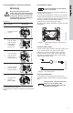
5.2 Changing the control box position
Procedure:
5.2.1 Control box position
For permissible control box positions, see the Quick
Guide.
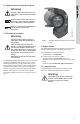
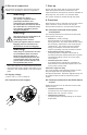
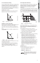
5.3 Insulation shells
Insulation shells for pumps in heating systems are
supplied with the pump.
For cold water applications, a silicone RTV sealant
must be liberally applied to the area shown in fig. 3
to prevent condensation between the shell and pump
housing. Follow the sealant manufacturers
instructions for safety and proper usage.
The fitting of insulation shells will increase the pump
dimensions.
Fig. 3 Shaded area indicates silicone RTV
sealant
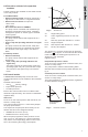
5.4 Non-return valve
If a non-return valve is fitted in the pipe system, see
fig. 4; ensure that the set minimum discharge
pressure of the pump is always higher than the
closing pressure of the valve. This is especially
important in proportional-pressure control mode
(reduced head at low flow).
Fig. 4 Non-return valve
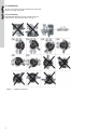
5.5 Frost protection
If the pump is not used during periods of frost,
necessary steps must be taken to prevent bursting
pipes.
Warning
Before any dismantling of the
pump, the system must be drained
or the isolating valves on both sides
of the pump must be closed as the
pumped liquid may be scalding hot
and under high pressure.
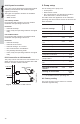
Step Action Illustration
1
Remove the two
screws.
TM03 0474 5204
2
Pull the stator
and the pump
head approx.
0.22 inches
(5 mm) out.
TM03 0475 5204
3
Turn the stator
and the pump
head to the
desired position.
TM03 0476 5204
4
Push the stator
and the pump
head into place.
TM03 0475 5204
5
Refit the two
screws
(16 + 5 Nm).
TM03 0580 0305
11RWH
It is recommended to fit insulation
shells to the pump.
TM04 9313 3910TM02 0640 0301
11RWH
Additives with a density and/or kin-
ematic viscosity higher than
those/that of water will reduce the
hydraulic performance.