GRUNDFOS DATA BOOKLET MAGNA1 Circulator pumps 60 Hz
MAGNA1 Table of contents 1. 2. 3. 4. 5. 6. 7. 8. 9.
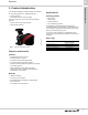
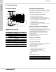
1 MAGNA1 TM05 5863 4112 The Grundfos MAGNA1 circulator pumps are designed for circulating liquids in the following systems: • heating systems • air conditioning and cooling systems. The pump range can also be used for the following systems: • ground source heat pump systems • solar heating systems. Fig. 1 Single-head MAGNA1 pumps Product introduction 1. Product introduction Applications Heating systems • Main pump • Mixing loops • Heating surfaces • Air conditioning surfaces.
1 MAGNA1 Product introduction System applications Heating systems • • • • • • • • • • • M M M M Out In TM01 0168 0697 M One- and two-pipe heating systems Main pumps Zone pumps Mixing loops Boiler shunt pumps Pumps for heating surfaces Calorifiers Underfloor heating systems Solar heating systems Ground source heat pump systems Heat recovery systems. Domestic hot-water systems • Domestic hot-water systems.
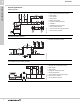
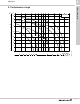
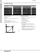
2 MAGNA1 H [m] H [ft] Performance range 2. Performance range MAGNA1 60 50 40-180 65-150 50-150 40 100-120 40-120 10 9 30 80-100 8 32-100 7 65-120 6 20 5 32-60 40-80 15 4 50-80 12 3 10 8 6 10 15 20 30 40 50 60 70 80 100 150 200 300 400 Q [US GPM] 3 Fig.
3 MAGNA1 Product range 3.
4 MAGNA1 Identification 4.
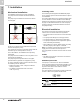
5 MAGNA1 Construction 5. Construction Mechanical construction TM05 2319 3012 Sectional drawing Fig. 4 MAGNA1 flanged version with PPS-composite rotor can Material specification See fig. 4. Pos. Component Material 1 Outer bearing ring Aluminium oxide 2 Control box Polycarbonate Stator housing Aluminium 3 EN O-rings/gaskets EPDM 4 Thrust bearing Aluminium oxide/carbon 5 Bearing plate Stainless steel EN 1.4301 6 Neck ring Stainless steel EN 1.
6 MAGNA1 Pumped liquids The pump is suitable for thin, clean, non-aggressive and non-explosive liquids, not containing solid particles or fibers that may attack the pump mechanically or chemically. In heating systems, the water should meet the requirements of accepted standards on water quality in heating systems. In domestic hot-water systems, we recommend to use MAGNA1 pumps only for water with a degree of hardness lower than approx. 14 °dH.
7 MAGNA1 Installation 7. Installation Mechanical installation Insulating shells The MAGNA1 is designed for indoor installation. The pump must be installed with horizontal motor shaft. The pump may be installed in horizontal as well as vertical pipes. The insulating shells supplied with MAGNA1 pumps are for heating systems and should be fitted as part of the installation.
7 MAGNA1 Installation Connection diagrams External switch Fuse (min. 10 A, time lag) TM03 2397 3712 ELCB Fig.
8 MAGNA1 Functions 8. Functions Selection of control mode System application In systems with relatively large pressure losses in the distribution pipes and in air conditioning and cooling systems.
8 MAGNA1 Control modes H CP3 Selection of pump setting for system type CP2 Factory setting: Intermediate proportional-pressure curve, referred to as PP2. CP1 Q Proportional pressure curve (PP1, PP2 or PP3) Proportional pressure control adjusts the pump performance to the actual heat demand in the system, but the pump performance follows the selected performance curve, PP1, PP2 or PP3. See fig. 8 where PP2 has been selected. See Selection of control mode on page 12 for further information.
8 MAGNA1 Functions Control panel Light fields indicating the pump setting The pump has nine optional performance settings which can be selected with the push-button. See fig. 11, pos. 3. The pump setting is indicated by eight light fields in the display. See fig. 11, pos. 2. 1 TM05 5553 3812 2 TM05 5552 3812 3 Fig. 12 Factory setting, PP2 Button presses Fig. 11 Control panel at first start-up The control panel on the pump comprises the following: Pos.
8 MAGNA1 Functions Overview of settings H PP3 CP3 PP2 CP2 CP1 II I III Q TM05 2777 0512 PP1 Fig. 13 Pump setting in relation to pump performance Setting PP1 PP2 PP3 CP1 CP2 CP3 III II I Pump curve Function The duty point of the pump will move up or down on the lowest proportional pressure curve, depending on the heat demand. See fig. 13. The head (pressure) is reduced at falling heat demand and increased at rising heat demand.
9 MAGNA1 Guide to performance curves 9. Guide to performance curves Each pump setting has its own performance curve (Q/H curve). A power curve (P1 curve) belongs to each Q/H curve. The power curve shows the pump power consumption (P1) in Watt at a given Q/H curve. The P1 value corresponds to the value that can be read from the pump display. See fig. 14. H PP3 CP3 PP2 CP2 PP1 CP1 II III I Q P1 III I Q Fig.
9 Curve conditions Guide to performance curves MAGNA1 Index 100 90 80 70 60 50 Typical Typical circulator circulator pump pump EuP EuP 2013 2013 EuP EuP 2015 2015 MAGNA1 EuP EuP MAGNA3 benchmark benchmark level level TM05 3935 1712 0 EEI = 0.17 10 EEI = 0.20 30 20 EEI = 0.23 40 labelled EEI = 0.27 The guidelines below apply to the performance curves. • Test liquid: airless water. • The curves apply to a density of ρ = 61.38 lb/ft3 (983.2 kg/m3) and a liquid temperature of +140 °F (+60 °C).
10 Performance curves and technical data MAGNA1 Performance curves and technical data 10. Performance curves and technical data MAGNA1 32-60 F (N) H [m] 8 6 1 x 115-230 V, 50/60 Hz H [ft] MAGNA1 32-60 F (N) 25 20 15 4 10 2 5 0 0 0 P1 [W] 5 10 0 15 2 20 III II I 25 4 30 6 35 Q [US GPM] 8 Q [m³/h] 120 III 100 80 TM06 0661 0714 II 60 40 20 I 0 0 5 10 Speed I1/1 [A] Min. 0.28 8.70 Max. 1.01 107.
Performance curves and technical data MAGNA1 32-100 F (N) H [m] 10 Performance curves and technical data MAGNA1 1 x 115-230 V, 50/60 Hz H [ft] MAGNA1 32-100 F (N) 35 10 30 8 25 20 6 15 4 10 2 III 5 0 I 0 0 P1 [W] II 5 10 0 15 2 20 25 4 30 35 6 40 Q [US GPM] 8 10Q [m³/h] 200 III 160 120 II TM06 0663 0714 80 40 I 0 0 5 10 Speed I1/1 [A] Min. 0.28 8.62 Max. 1.61 178.
10 Performance curves and technical data MAGNA1 Performance curves and technical data MAGNA1 40-80 F (N) H [m] 1 x 115 & 208-230 V, 50/60 Hz H [ft] MAGNA1 40-80 F (N) 30 8 25 20 6 15 4 10 2 5 0 I 0 0 5 10 0 P1 [W] 15 2 20 25 4 30 6 35 III II 40 8 45 50 10 55 60 12 65 70 14 Q [US GPM] 16 18Q [m³/h] III 250 200 II 150 50 TM05 8799 2713 100 I 0 0 Speed I1/1 [A] 115 V P1 [W] 115 V 5 10 15 I1/1 [A] 230 V 20 25 30 35 40 Min. 0.3 16 0.19 16 2.
Performance curves and technical data MAGNA1 40-120 F (N) H [m] H [ft] 12 40 10 Performance curves and technical data MAGNA1 1 x 115 & 208-230 V, 50/60 Hz MAGNA1 40-120 F (N) 35 10 30 8 25 20 6 15 4 10 2 0 I 0 0 P1 [W] III II 5 5 0 10 15 20 25 30 35 40 45 50 55 60 65 70 75 80 85 90 Q [US GPM] 2 22Q 4 6 8 10 12 14 16 18 20 500 [m³/h] III 400 300 II TM05 8800 2713 200 100 I 0 0 P1 [W] 115 V 5 10 15 20 25 30 35 40 45 50 55 60 65 70 75 80 85 90 Q Speed I1/1 [A] 1
10 Performance curves and technical data MAGNA1 Performance curves and technical data MAGNA1 40-180 F (N) H [m] 1 x 115 & 208-230 V, 50/60 Hz H [ft] MAGNA1 40-180 F (N) 60 50 15 40 10 30 20 5 10 0 0 0 P1 [W] III II I 10 20 0 30 40 5 50 60 10 70 80 15 90 100 Q [US GPM] 20 25 Q [m³/h] III 600 500 400 II 300 100 TM05 8801 2713 200 I 0 0 10 P1 [W] 115 V 20 30 I1/1 [A] 230 V 40 Speed I1/1 [A] 115 V Min. 0.26 16 0.18 16 Max. 5.39 614 2.
Performance curves and technical data MAGNA1 50-80 F (N) H [m] 10 Performance curves and technical data MAGNA1 1 x 115 & 208-230 V, 50/60 Hz H [ft] MAGNA1 50-80 F (N) 30 8 25 20 6 15 4 10 2 5 0 0 0 P1 [W] 10 20 0 30 40 5 III II I 50 60 10 70 80 90 15 100 20 Q [US GPM] 25 Q [m³/h] 350 III 300 250 II 200 TM05 8802 2713 150 100 50 I 0 0 10 20 30 40 Speed I1/1 [A] 115 V P1 [W] 115 V I1/1 [A] 230 V P1 [W] 230 V Min. 0.31 18.5 0.22 18.5 Max. 2.
10 Performance curves and technical data MAGNA1 Performance curves and technical data MAGNA1 50-150 F (N) H [m] H [ft] 15 50 1 x 115 & 208-230 V, 50/60 Hz MAGNA1 50-150 F (N) 40 10 30 20 5 10 0 0 0 P1 [W] 10 20 0 30 40 5 III II I 50 60 10 70 80 15 90 100 110 120 130 140Q 20 25 30 [US GPM] Q [m³/h] 700 III 600 500 II 400 TM05 8803 2713 300 200 100 I 0 0 10 20 30 40 50 Speed I1/1 [A] 115 V P1 [W] 115 V I1/1 [A] 230 V P1 [W] 230 V Min. 0.31 18.5 0.
Performance curves and technical data MAGNA1 65-120 F (N) H [m] H [ft] 12 40 10 Performance curves and technical data MAGNA1 1 x 115 & 208-230 V, 50/60 Hz MAGNA1 65-120 F (N) 35 10 30 8 25 20 6 15 4 10 2 5 0 P1 [W] 0 20 0 5 40 60 10 80 15 III II I 0 100 20 120 25 140 160 30 180Q 35 [US GPM] 40 Q [m³/h] 800 III 600 TM05 8804 2713 II 400 200 I 0 0 Speed I1/1 [A] 115 V P1 [W] 115 V Min. 0.36 Max. 6.67 20 40 60 I1/1 [A] 230 V P1 [W] 230V 20.5 0.
10 Performance curves and technical data MAGNA1 Performance curves and technical data MAGNA1 65-150 F (N) H [m] H [ft] 15 50 1 x 208-230 V, 50/60 Hz MAGNA1 65-150 F (N) 40 10 30 20 5 10 0 0 P1 [W] 0 20 0 5 40 60 10 80 15 III II I 100 20 120 25 140 30 160 180 35 40 200 Q [US GPM] 45 50 Q [m³/h] III 1200 1000 800 II TM05 8805 2713 600 400 200 I 0 0 Speed 20 40 P1 [W] 60 80 100 120 Min. 29 0.30 1301 5.
Performance curves and technical data MAGNA1 80-100 F (N) H [m] 10 10 Performance curves and technical data MAGNA1 1 x 208-230 V, 50/60 Hz H [ft] MAGNA1 80-100 F (N) 35 30 8 6 4 25 20 15 10 2 III 5 0 I 0 P1 [W] II 0 20 0 5 40 60 10 80 15 100 20 120 25 140 160 30 180 35 40 200 Q [US GPM] 45 50 Q [m³/h] III 1000 800 600 II TM05 8806 2713 400 200 I 0 0 Speed 20 40 P1 [W] 60 80 100 120 Min. 31 0.32 1041 4.
10 Performance curves and technical data MAGNA1 Performance curves and technical data MAGNA1 100-120 F (N) H [m] H [ft] 12 40 1 x 208-230 V, 50/60 Hz MAGNA1 100-120 F (N) 35 10 30 8 25 6 20 15 4 10 2 III 5 0 P1 [W] II I 0 0 20 0 5 40 60 10 80 15 100 20 120 25 140 30 160 35 180 200 220 240 260 Q 40 45 50 55 60 [US GPM] Q [m³/h] III 1400 1200 1000 800 TM05 8807 2713 II 600 400 200 I 0 0 Speed 20 40 60 P1 [W] 80 100 120 140 Min. 31 0.
Performance curves and technical data 10 Performance curves and technical data MAGNA1 Technical data Electrical data Pump type MAGNA1 Enclosure class Type 2, IPX4D(EN 60529). Insulation class F. Supply voltage 1x115V ± 10 % 50/60 Hz, 1x208-230V ± 10 % 50/60 Hz. Leakage current Ileakage < 3.5 mA. The leakage current is measured in accordance with EN 60335-1. EMC EN 55014-1:2006, EN 55014-2:1998, EN 61800-3-3:2008 and EN 61000-3-2:2006.
11 MAGNA1 Further product documentation 11. Further product documentation WebCAPS WebCAPS is a Web-based Computer Aided Product Selection program available on www.grundfos.com. WebCAPS contains detailed information on more than 220,000 Grundfos products in more than 30 languages. Information in WebCAPS is divided into six sections: • Catalog • Literature • Service • Sizing • Replacement • CAD drawings.
Sizing 0 Further product documentation 11 MAGNA1 1 This section is based on different fields of application and installation examples and gives easy step-by-step instructions in how to size a product: • Select the most suitable and efficient pump for your installation. • Carry out advanced calculations based on energy, consumption, payback periods, load profiles, life cycle costs, etc. • Analyze your selected pump via the built-in life cycle cost tool.
11 MAGNA1 Further product documentation GO CAPS Mobile solution for professionals on the GO! CAPS functionality on the mobile workplace. Subject to alterations.
© Copyright Grundfos Holding A/S ECM: 1130603 Grundfos Kansas City 17100 West 118th Terrace Olathe, Kansas 66061 Phone: 913-227-3400 Fax: 913-227-3500 www.grundfos.us Grundfos Canada 2941 Brighton Road Oakville, Ontario L6H 6C9 Canada Phone: +1-905-829-9533 Fax: +1-905-829-9512 www.grundfos.ca Grundfos México Boulevard TLC No. 15 Parque Industrial Stiva Aeropuerto C.P. 66600 Apodaca, N.L. Mexico Phone: 011-52-81-8144 4000 Fax: 011-52-81-8144 4010 www.grundfos.