
Brochure

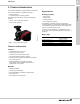
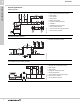
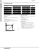
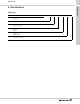
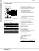
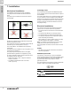
Table Of Contents

Installation
MAGNA1
7
10
7. Installation
Mechanical installation
The MAGNA1 is designed for indoor installation.
The pump must be installed with horizontal motor
shaft.
The pump may be installed in horizontal as well as
vertical pipes.
Fig. 5 Installation positions
Arrows on the pump housing indicate the liquid flow
direction through the pump.
The control box must be in horizontal position with the
Grundfos logo in vertical position. See fig. 5.
This is described in the installation and operating
instructions.
The pump must be installed in such a way that it is not
stressed by the pipework.
The pump may be suspended direct in the pipes,
provided that the pipework can support the pump.
To ensure adequate cooling of motor and electronics,
the following must be observed:
• Position the pump in such a way that sufficient
cooling is ensured.
• The ambient temperature must not exceed
+104 °F (+40 °C).
Insulating shells
The insulating shells supplied with MAGNA1 pumps
are for heating systems and should be fitted as part of
the installation.
For cooling applications, if the supplied insulation shell
is to be used then a silicon sealant must be liberally
applied to the inside of the insulation shell to ensure all
air gaps are eliminated between the shell and pump
housing to prevent condensation between the shell
and pump housing.
Electrical installation
The electrical connection and protection should be
carried out in accordance with local regulations.
• The pump must be connected to an external mains
switch.
• The pump must always be correctly grounded.
• The pump requires no external motor protection.
• The pump incorporates thermal protection against
slow overloading and blocking.
• When switched on via the power supply, the pump
will start pumping after approx. 5 seconds.
Note: The number of starts and stops via the power
supply must not exceed four times per hour.
The pump mains connection must be made as shown
in fig. 6.
Cables
• All cables used must be connected in accordance
with local regulations.
Additional protection
If the pump is connected to an electric installation
where an earth leakage circuit breaker (ELCB) is used
as an additional protection, this circuit breaker must
trip when earth fault currents with DC content
(pulsating DC) occur.
The earth leakage circuit breaker must be marked with
the first or both of the symbols shown below:
TM05 5518 3812
Symbol Description
High-sensitivity ELCB, type A, according to
IEC 60775
High-sensitivity ELCB, type B, according to
IEC 60775