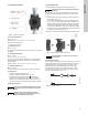
GRUNDFOS INSTRUCTIONS MAGNA3 Installation and operating instructions
English (US) English (US) Installation and operating instructions Original installation and operating instructions. CONTENTS Page 1. Limited warranty 3 2. Symbols used in this document 3 3. 3.1 3.2 3.3 3.4 3.5 3.6 3.7 3.8 3.9 General information Applications Pumped liquids Operating conditions Frost protection Insulating shells Non-return valve Nameplate Radio communication Tools 4 4 4 5 5 5 5 6 7 7 4. 4.1 4.2 4.3 4.4 4.
2. Symbols used in this document Products manufactured by GRUNDFOS PUMPS CORPORATION (Grundfos) are warranted to the original user only to be free of defects in material and workmanship for a period of 24 months from date of installation, but not more than 30 months from date of manufacture. Grundfos' liability under this warranty shall be limited to repairing or replacing at Grundfos' option, without charge, F.O.B. Grundfos' factory or authorized service station, any product of Grundfos' manufacture.
Max. 95 % RH The Grundfos MAGNA3 is a complete range of circulator pumps with integrated controller enabling adjustment of pump performance to the actual system requirements. In many systems, this will reduce the power consumption considerably, reduce noise from thermostatic radiator valves and similar fittings and improve the control of the system. Enclosure Type 2 TM05 2857 0612 English (US) 3. General information The desired head can be set on the pump control panel. 3.
English (US) 3.5 Insulating shells 3.3 Operating conditions Insulating shells are available for single-head pumps only. Note 1 Min./Max. +14 °F - 230 °F (-10 °C - +110 °C) 175 psi (12 bar) 3 +32 to +104 °F (0 to +40 °C) 4 < 43 dB(A) Fig. 2 The heat loss from the pump and pipework can be reduced by insulating the pump housing and the pipework. See fig. 3 and fig. 13. TM05 7662 1413 2 Limit the heat loss from the pump housing and pipework.
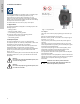
The pump nameplate provides the following information: TYPE 2 BOITIER DE TYPE 2 THERMALLY PROTECTED Nonsubmersible Pump PSI For use with maximum 230° F water RISK OF ELECTRIC SHOCK. DE-ENERGIZE EQUIPMENT BEFORE REMOVAL OF COVER & SERVICING. FOR SUPPLY CONNECTION USE COPPER WIRE SUITABLE FOR 90 °C OR EQUIVALENT. THIS PUMP HAS NOT BEEN INVESTIGATED FOR USE IN SWIMMING POOL OR MARINE AREAS. TO REDUCE THE RISK OF ELECTRIC SHOCK, SEE INSTRUCTION MANUAL FOR PROPER INSTALLATION; ACCEPTABLE FOR INDOOR USE ONLY.
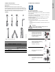
English (US) 4. Mechanical installation 3.8 Radio communication The wireless radio in this product is class B. Intended use This product incorporates a radio for remote control. The product can communicate with Grundfos Go Remote and with other MAGNA3 pumps of the same type via the built-in radio. Only Grundfos-approved external antennae may be connected to this product, and only by a Grundfos-approved installer. MAGNA3 is designed for indoor installation. 3.9 Tools 1.2 x 8.0 4.
If the pump head is removed before the pump is installed in the pipework, pay special attention when fitting the pump head to the pump housing: Always install the pump with horizontal motor shaft. • Pump installed correctly in a vertical pipe. See fig. 7, pos. A. • Pump installed correctly in a horizontal pipe. See fig. 7, pos. B. • Do not install the pump with vertical motor shaft. See fig. 7, pos. C and D. B C D Fig.
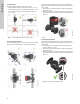
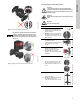
Warning The warning symbol on the clamp holding the pump head and pump housing together indicates that there is a risk of personal injury. See specific warnings below. Warning When loosening the clamp, do not drop the pump head. Risk of escaping vapor. 4 Due to the drain hole in the stator housing, position the gap of the clamp as shown in step 4a, 4b, 4c or 4d. Fig. 12 Fitting the pump head to the pump housing 4a Single-head pump. Position the clamp so that the gap points towards the arrow.
6 7 Twin-head pump. Note: The gap of the clamp can also be in position 6 o'clock for the following pump sizes: • MAGNA3 65-XX • MAGNA3 80-XX • MAGNA3 100-XX. Fit and tighten the screw holding the clamp to minimum 6 ± 0.7 ft-lbs (8 ± 1 Nm). Fit the insulating shells. Note: For air conditioning and cooling systems a silicone sealant must be applied inside the insulation shell to eliminate all air gaps and prevent condensation between the pump housing and insulation shell.
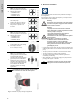
Step Action 1 x 115 V ± 10 %, 50/60 Hz, PE. English (US) 5.1 Supply voltage Illustration 1 x 208-230 V ± 10 %, 50/60 Hz, PE. 7 Insert the power supply plug into the male plug in the pump control box. 8 Tighten the conduit adapter. Refit the front cover. 5.2 Connection to the power supply (models 40-XX, 50-XX, 65-XX, 80-XX, 100-XX) 3 Connect the conduit adapter to the control box. 4 Pull the power supply cable through the conduit adapter. 5 Strip the cable conductors as illustrated.
7 L (L1) 2 Locate the power plug inside. N (L2) 3 Pull the power supply cable through the conduit. TM06 1104 1614 Connect the conduit to the control box. 5 6 Connect the cable conductors to the power supply plug. L - L or L1 Ground - Ground N - N or L2 Insert the power plug into its mating connector. Tighten the conduit. 12 TM06 1105 1614 Strip the cable as illustrated. Refit the front cover. TM06 1107 1614 Remove two screws.
English (US) 5.4 Connection diagram External switch GFCI Fuse TM03 2397 0312 (min. 10 A, time lag) Fig. 14 Example of typical connection, 1 x 230 V ± 10 %, 50/60 Hz Note All cables used must be connected in accordance with local regulations. 5.4.1 Connection to external controllers Analog input IN 24V Vcc signal sensor M A M I S/S NC NO C NC NO C L Alarm N Mains connection Operation On/off timer TM05 2673 3812 Start/ stop Fig.
TM05 8539 2413 English (US) Fig. 16 Wiring diagram, 32-XX versions The connection terminals of 32-XX versions differ from those of terminal-connected versions, but they have the same function and connection options. Use screened cables for external on/off switch, digital input, sensor and setpoint signals. Connect screened cables to the ground connection as follows: • Terminal-connected versions: Connect the cable screen to ground via the digital-input terminal (earth).
5.5 Input/output communication • Relay outputs Alarm, ready and operating indication via signal relay. • Digital input Signal relay – Start/Stop (S/S) 1 2 3 NC NO C 1 2 3 NC NO C – Min. curve (MI) – Max. curve (MA). • Analog input 0-10 V or 4-20 mA control signal. To be used for external control of the pump or as sensor input for the control of the external setpoint. The 24 V supply from pump to sensor is optional and is normally used when an external supply is not available.
External forced max. or min. curve See fig. 15, pos. 2. The pump can be forced to operate on the max. or min. curve via the digital input. The digital input can be used for external control of start/stop or forced max. or min. curve. If no external on/off switch is connected, the jumper between terminals Start/Stop (S/S) and frame ( ) should be maintained. This connection is the factory setting. M A Max. curve M A H Normal duty Q M I S/S M A H Max. curve Q Min.
English (US) 5.6 Analog input for external sensor 1 The analog input can be used for the connection of an external sensor for measuring temperature or pressure. The analog input can also be used for an external signal for the control from a BMS system or similar control system. 24V The electrical signal for the input can be 0-10 VDC or 4-20 mA. IN Vcc Signal The selection of electrical signal (0-10 V or 4-20 mA) can be changed on the control panel or with Grundfos GO Remote. 2 signal sensor Fig.
5.8 Priority of settings The external forced-control signals will influence the settings available on the pump control panel or with Grundfos GO Remote. However, the pump can always be set to max. curve duty or to stop on the pump control panel or with Grundfos GO Remote. 2 1 If two or more functions are enabled at the same time, the pump will operate according to the setting with the highest priority. 4 The priority of the settings is as shown in the table below.
English (US) 6. First start-up Do not start the pump until the system has been filled with liquid and vented. Furthermore, the required minimum inlet pressure must be available at the pump inlet. See section 19. Technical data. The system cannot be vented through the pump. The pump is self-venting. 1 Switch on the power supply to the pump. Note: When switched on, the pump will start in AUTOADAPT after approx. 5 seconds. 2 Pump display at first start-up.
English (US) 7. Settings 7.1 Overview of settings All settings can be made on the pump control panel or with Grundfos GO Remote. Menu Submenu Further information Setpoint See section 13.1 Setpoint. Operating mode See section 13.2 Operating mode. • Normal • Stop • Min. • Max. Control mode See section 13.3 Control mode. • AUTOADAPT See section 13.3.1 AUTOADAPT. • FLOWADAPT See section 13.3.2 FLOWADAPT. • Prop. press. See section 13.3.3 Proportional pressure. • Const. press. See section 13.3.
Status Settings Assist Operating status Setpoint Assisted pump setup Operating mode, from Operating mode Control mode Control mode Pump performance Setting of pump Setting of date and time Date format, date and time FLOWLIMIT Max.
10. Menu structure The pump incorporates a start-up guide which is started at the first start-up. After the start-up guide, the four main menus will appear in the display. See section 6. First start-up. Warning At high liquid temperatures, the pump housing may be very hot. In that case, only touch the control panel. 1. Home This menu shows up to four user-defined parameters with shortcuts or a graphical illustration of a Q/H performance curve. See section 11. "Home" menu. 2.
3.1.0.0.0.0 Settings English (US) 13. "Settings" menu 2.1.0.0.0.0 Status 12. "Status" menu Navigation Navigation Home > Status Press Home > Settings and go to the "Status" menu with . Press and go to the "Settings" menu with .
3.1.3.0.0.0 Control mode 3.1.2.0.0.0 Operating mode 13.3 Control mode Navigation Navigation Home > Settings > Operating mode Home > Settings > Control mode Operating mode Control mode • Normal (control mode) • AUTOADAPT • Stop • FLOWADAPT • Min. (min. curve) • Prop. press. (proportional pressure) • Max. (max. curve). • Const. press. (constant pressure) • Const. temp.(constant temperature) • Constant curve. Setting: 1. Select operating mode with or . 2. Press [OK] to save.
13.3.2 FLOWADAPT The AUTOADAPT control mode continuously adapts the pump performance according to the actual system characteristic. When FLOWADAPT is selected, the pump will run AUTOADAPT and ensure that the flow never exceeds the entered FLOWLIMIT value. Note The setting range for the FLOWLIMIT is 25 to 90 % of the Qmax of the pump. Manual setting of the setpoint is not possible. The factory setting of the FLOWLIMIT is the flow where the AUTOADAPT factory setting meets the max. curve. See fig. 27.
13.3.6 Differential temperature The pump maintains a constant pressure, irrespective of water demand. See fig. 29. This control mode ensures a constant differential temperature drop across a heating system. The pump should be installed in the flow pipe so the built-in sensor measures the liquid temperature going out to the load. An external temperature sensor must be installed in the system to measure the liquid temperature returning from the heating load.
13.3.7 Constant curve The table shows the suggested controller settings: The pump can be set to operate according to a constant curve, like an uncontrolled pump. See fig. 34. Kp System/application Heating system 1) Cooling system 2) Ti 0.5 - 0.5 10 + 5L2 t English (US) See table, fig. 33. The desired speed can be set in % of maximum speed in the range from 25 to 100 %. H -0.5 Δt 10 + 5L2 L2 [m] Q Fig. 34 Constant curve L2 [m] 0.5 - 0.5 30 + 5L2 Note Fig.
3.1.6.0.0.0 Automatic Night Setback 3.1.5.0.0.0 FLOWLIMIT Navigation Navigation Home > Settings > FLOWLIMIT Home > Settings > Automatic Night Setback FLOWLIMIT Automatic Night Setback • Enable FLOWLIMIT function • Set FLOWLIMIT. To enable the function, select "Active" with [OK]. Setting: 1. To enable the function, select "Active" with [OK]. or and press 3. Select digit with and and adjust with or .
Navigation Navigation Home > Settings > Relay outputs Home > Settings > Setpoint influence Relay outputs Setpoint influence • Relay output 1 • External setpoint function • Relay output 2. • Temperature influence. The relay outputs can be set to the following: 13.7.1 External setpoint function • Not active • Ready Range • Alarm Operation.
13.8 Bus communication When this function is enabled in proportional- or constant-pressure control mode, the setpoint for head will be reduced according to the liquid temperature. 13.8.1 Pump number H 3.1.18.1.0.0 Pump number Temperature influence can be set to function at liquid temperatures below +176 °F or +122 °F (80 °C or 50 °C). These temperature limits are called Tmax.. The setpoint is reduced in relation to the head set (= 100 %) according to the characteristics below.
13.9.2 Set date and time 3.1.19.3.0.0 Units 3.1.19.2.0.0 Set date and time English (US) 13.9.3 Units Navigation Navigation Home > Settings > General settings > Set date and time Home > Settings > General settings > Units Set date and time Units • Select date format • SI or US units • Set date • Customized units. • Select time format • Set time. Select whether the display should shows SI or US units or select the desired units for the parameters below.
3.1.19.6.0.0 Define Home display 3.1.19.4.0.0 Enable/disable settings 13.9.6 Define Home display Navigation Navigation Home > Settings > General settings > Enable/disable settings Home > Settings > General settings > Define Home display Enable/disable settings Define Home display In this display, the possibility of making settings can be disabled for protective reasons. • Select Home display type • Define Home display contents.
Navigation Navigation Home > Settings > General settings > Display brightness Home > Settings > General settings > Run start-up guide Brightness Run start-up guide 1. Press [OK] to start the setting. 2. Set brightness with and It is possible to run the start-up guide again. The start-up guide will guide the user through the general settings of the pump, such as language, date and time. . 3. Press [OK] to save. To run the start-up guide, select "Yes" with [OK]. or and press 3.1.19.10.1.
14.7 Wireless GENIair The pump is designed for multi-pump connection via the wireless GENIair connection or wired via a bus system (Building Management System). The built-in wireless GENIair module enables communication between pumps and with Grundfos Go Remote without the use of add-on modules: Assist English (US) 14. "Assist" menu Navigation Home > Assist Press and go to the "Assist" menu with . "Assist" menu This menu offers the following: • Multi-pump function. See section 14.
System application Recommended for most heating systems, especially in systems with relatively large pressure losses in the distribution pipes. See description under proportional pressure. In replacement situations where the proportional-pressure duty point is unknown. The duty point has to be within the AUTOADAPT operating range. During operation, the pump automatically makes the necessary adjustment to the actual system characteristic.
English (US) System application Select this control mode Constant temperature In heating systems with a fixed system characteristic, for example domestic hot-water systems, the control of the pump according to a constant return-pipe temperature may be relevant. FLOWLIMIT can be used with advantage to control the maximum circulation flow. H Q Differential temperature In a heating system where a constant temperature drop across the system is desired, constant differential temperature can be used.
English (US) 16. Fault finding Warning Before dismantling the pump, drain the system or close the isolating valve on either side of the pump. The pumped liquid may be scalding hot and under high pressure. 16.1 Grundfos Eye operating indications Grundfos Eye Indication Cause No lights on. Power off. Pump not running. Two opposite green indicator lights running in the Power on. direction of rotation of the pump. Pump running. Two opposite green indicator lights permanently Power on. on.
English (US) 16.3 Fault finding A fault indication can be reset in one of the following ways: • When the fault cause has been eliminated, the pump will revert to normal duty. • If the fault disappears by itself, the fault indication will automatically be reset. • The fault cause will be stored in the pump alarm log. Warning and alarm codes Fault Pump communication fault (10) Alarm Communication fault between different parts of the electronics.
English (US) 17. Sensor 5 Nm TM05 3036 0812 Nose downwards Fig. 39 Correct position of sensor During maintenance and replacement of the sensor, it is important that the sealing cap is fitted correctly on the sensor housing. Tighten the screw holding the clamp to 3.7 ft-lbs (5 Nm). Warning Before replacing the sensor, make sure that the pump is stopped and that the system is not pressurized. 17.1 Sensor specifications 17.1.1 Pressure Maximum differential pressure during operation 29 psi / 2 bar / 0.
18.2 Communication The pump can communicate via the wireless GENIair connection or a CIM module. This enables the pump to communicate with other pumps and with different types of network solutions. 18.1 Grundfos GO Remote The Grundfos CIM modules (CIM = Communication Interface Module) enable the pump to connect to standard fieldbus networks. MAGNA3 is designed for wireless communication with the Grundfos GO Remote app.
Module English (US) 18.2.1 Description of CIM modules Fieldbus protocol Description Functions GENIbus CIM 050 is a Grundfos communication interface module used for communication with a GENIbus network. CIM 050 has terminals for the GENIbus connection. LonWorks CIM 100 is a Grundfos communication interface module used for communication with a LonWorks network. CIM 100 has terminals for the LonWorks connection. Two LEDs are used to indicate the actual status of the CIM 100 communication.
English (US) Fieldbus protocol Module Description Functions TM05 4432 2212 CIM 270 CIM 270 is a Grundfos GSM/GPRS modem used for communication with a Grundfos Remote Grundfos Remote Management system. Management It requires a GSM antenna, a SIM card and a contract with Grundfos. With CIM 270 you have wireless access to your account anywhere, anytime when you have an internet connection, for example via a smartphone, tablet PC, laptop or computer.
English (US) 18.3 Fitting the CIM module Warning Before fitting the module, switch off the power supply. Make sure that the power supply cannot be accidentally switched on. Step Action Remove the front cover from the control box. 2 Fit the CIM module as illustrated and click it on. 3 Fit and tighten the screw holding the CIM module and secure the earth connection. 4 For connection to fieldbus networks, see separate installation and operating instructions for the desired CIM module.
English (US) 19. Technical data Input/output communication Supply voltage See Pump Nameplate for Rated Supply Voltage: 1 x 115 V ± 10 %, 50/60 Hz, PE. Two digital inputs External potential-free contact. Contact load: 5 V, 10 mA. Screened cable. Loop resistance: Maximum 130 Ω. Analog input 4-20 mA (load: 150 Ω). 0-10 VDC (load: 78 kΩ). Two relay outputs Internal potential-free changeover contact. Maximum load: 250 V, 2 A, AC1. Minimum load: 5 VDC, 20 mA. Screened cable, depending on signal level.
GRUNDFOS Canada GRUNDFOS México 17100 West 118th Terrace Olathe, Kansas 66061 Phone: (913) 227-3400 Fax: (913) 227-3500 2941 Brighton Road Oakville, Ontario L6H 6C9 Canada Phone: +1-905 829 9533 Telefax: +1-905 829 9512 Boulevard TLC No. 15 Parque Industrial Stiva Aeropuerto C.P. 66600 Apodaca, N.L. México Phone: 011-52-81-8144 4000 Fax: 011-52-81-8144 4010 www.grundfos.us www.grundfos.ca www.grundfos.
98459408 0614 ECM: 1133339 www.grundfos.com www.grundfos.us The name Grundfos, the Grundfos logo, and be think innovate are registered trademarks owned by Grundfos Holding A/S or Grundfos A/S, Denmark. All rights reserved worldwide.