
Install Instructions
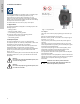
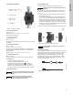
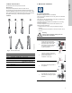
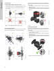
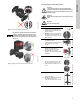
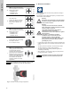
Table Of Contents
- English (US)
- 1. Limited warranty
- 2. Symbols used in this document
- 3. General information
- 4. Mechanical installation
- 5. Electrical installation
- 5.1 Supply voltage
- 5.2 Connection to the power supply (models 40-XX, 50-XX, 65-XX, 80-XX, 100-XX)
- 5.3 Connection to the power supply (models 32-XX)
- 5.4 Connection diagram
- 5.5 Input/output communication
- 5.6 Analog input for external sensor
- 5.7 Electrical connection for external sensor
- 5.8 Priority of settings
- 6. First start-up
- 7. Settings
- 8. Menu overview
- 9. Control panel
- 10. Menu structure
- 11. "Home" menu
- 12. "Status" menu
- 13. "Settings" menu
- 14. "Assist" menu
- 15. Selection of control mode
- 16. Fault finding
- 17. Sensor
- 18. Accessories
- 19. Technical data
- 20. Disposal

English (US)
10
Fig. 13 Insulation of pump housing and pipework
5. Electrical installation
Carry out the electrical connection and protection according to
local regulations.
Check that the supply voltage and frequency correspond to the
values stated on the nameplate.
• If rigid conduit is to be used, the hub must be connected to the
conduit system before it is connected to the terminal box of the
pump.
• The pump must be connected to an external mains switch.
• The pump requires no external motor protection.
• The motor incorporates thermal protection against slow
overloading and blocking.
• When switched on via the power supply, the pump will start
pumping after approx. 5 seconds.
4b
Single-head pump.
Note: The gap of the clamp can
also be in position 6 o'clock for the
following pump sizes:
• MAGNA3 65-XX
• MAGNA3 80-XX
• MAGNA3 100-XX.
TM05 2899 1912
4c
Twin-head pump.
Position the clamps so that the
gaps point towards the arrows.
They can be in position 3 or
9o'clock.
TM05 2917 0612 - TM05 2873 0612
4d
Twin-head pump.
Note: The gap of the clamp can
also be in position 6 o'clock for the
following pump sizes:
• MAGNA3 65-XX
• MAGNA3 80-XX
• MAGNA3 100-XX.
TM05 2897 1912
6
Fit and tighten the screw holding
the clamp to minimum
6 ± 0.7 ft-lbs (8 ± 1 Nm).
TM05 2872 0612
7
Fit the insulating shells.
Note: For air conditioning and
cooling systems a silicone sealant
must be applied inside the
insulation shell to eliminate all air
gaps and prevent condensation
between the pump housing and
insulation shell. Alternatively, the
pump may be insulated manually
in accordance with standard
insulation practices for cooling
applications.
TM05 2874 0412
Caution
If insulating the pump manually, do not insulate
the control box or cover the control panel.
TM05 5549 3812
Step Action Illustration
Warning
Never make any connections in the pump control
box unless the power supply has been switched
off for at least 5 minutes.
Warning
The pump must be connected to an external
mains switch with a contact separation of at least
1/8 inch (3 mm) in each pole.
The ground terminal of the pump must be
connected to ground. Grounding or
neutralization can be used for protection against
indirect contact.
If the pump is connected to an electric
installation where a Ground Fault Circuit
Interrupter (GFCI) is used as additional
protection, this circuit interrupter must trip out
when ground fault currents with DC content
(pulsating DC) occur.
Note
Note
The number of starts and stops via the power
supply must not exceed four times per hour.