
Install Instructions
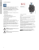
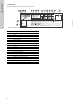
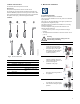
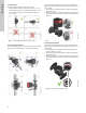
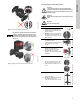
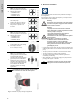
Table Of Contents
- English (US)
- 1. Limited warranty
- 2. Symbols used in this document
- 3. General information
- 4. Mechanical installation
- 5. Electrical installation
- 5.1 Supply voltage
- 5.2 Connection to the power supply (models 40-XX, 50-XX, 65-XX, 80-XX, 100-XX)
- 5.3 Connection to the power supply (models 32-XX)
- 5.4 Connection diagram
- 5.5 Input/output communication
- 5.6 Analog input for external sensor
- 5.7 Electrical connection for external sensor
- 5.8 Priority of settings
- 6. First start-up
- 7. Settings
- 8. Menu overview
- 9. Control panel
- 10. Menu structure
- 11. "Home" menu
- 12. "Status" menu
- 13. "Settings" menu
- 14. "Assist" menu
- 15. Selection of control mode
- 16. Fault finding
- 17. Sensor
- 18. Accessories
- 19. Technical data
- 20. Disposal

5
English (US)
3.3 Operating conditions
Fig. 2 Operating conditions
3.3.1 Liquid temperature
See fig. 2, pos. 1.
Continuously: +14 °F to +230 °F (-10 °C to +110 °C).
Domestic hot-water systems:
• Up to +150 °F (+65 °C).
3.3.2 System pressure
See fig. 2, pos. 2.
The maximum permissible system pressure is stated on the pump
nameplate.
3.3.3 Ambient temperature
See fig. 2, pos. 3.
+32 °F to +104 °F (0 °C to +40 °C).
The control box is air-cooled. Therefore, it is important that the
maximum permissible ambient temperature is not exceeded
during operation.
During transport: -40 °F to +158 °F (-40 °C to +70 °C).
3.3.4 Sound pressure level
See fig. 2, pos. 4.
The sound pressure level of the pump is lower than 43 dB(A).
3.3.5 Approvals
• Conforms to ANSI/UL Standard 778.
• Certified to CAN/CSA Standard C22.2 No. 108.
• The protective earth (ground) symbol identifies any
terminal which is intended for connection to an external
conductor for protection against electric shock in case of a
fault, or the terminal of a protective earth (ground) electrode.
3.4 Frost protection
3.5 Insulating shells
Insulating shells are available for single-head pumps only.
The heat loss from the pump and pipework can be reduced by
insulating the pump housing and the pipework. See fig. 3 and
fig. 13.
• Insulating shells for pumps in heating systems are supplied
with the pump; see fig. 3.
• For pumps in air-conditioning and cooling systems (down to
+14 ° (-10 °C)) it is required to apply a silicon sealant to the
internal contours of the shell in order to eliminate any air gaps
and prevent condensation between the insulation shell and
pump housing. Alternatively, the pump can also be insulated
manually in accordance with standard insulating requirements
for heating and cooling systems (fig. 13).
The fitting of insulating shells will increase the pump dimensions.
Fig. 3 Fitting insulating shells to the pump
3.6 Non-return valve
If a non-return valve is fitted in the pipe system (fig. 4), it must be
ensured that the set minimum discharge pressure of the pump is
always higher than the closing pressure of the valve. This is
especially important in proportional-pressure control mode
(reduced head at low flow). The closing pressure of a single
non-return valve is accounted for in the pump settings as the
minimum head delivered is 5 ft (1.5 m).
Fig. 4 Non-return valve
TM05 7662 1413
Caution
If the pump is not used during periods of frost,
necessary steps must be taken to prevent frost
bursts.
Note
Note
Additives with a density and/or kinematic
viscosity higher than those/that of water will
reduce the hydraulic performance.
Min./Max. +14 °F - 230 °F
(-10 °C - +110 °C)
175 psi (12 bar)
1
2
3
4
+32 to +104 °F
(0 to +40 °C)
< 43 dB(A)
Note
Note
Limit the heat loss from the pump housing and
pipework.
TM05 2859 0612
Caution
Do not insulate the control box or cover the
control panel.
TM05 3055 0912