
Install Instructions
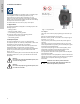
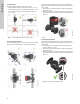
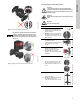
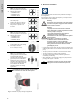
Table Of Contents
- English (US)
- 1. Limited warranty
- 2. Symbols used in this document
- 3. General information
- 4. Mechanical installation
- 5. Electrical installation
- 5.1 Supply voltage
- 5.2 Connection to the power supply (models 40-XX, 50-XX, 65-XX, 80-XX, 100-XX)
- 5.3 Connection to the power supply (models 32-XX)
- 5.4 Connection diagram
- 5.5 Input/output communication
- 5.6 Analog input for external sensor
- 5.7 Electrical connection for external sensor
- 5.8 Priority of settings
- 6. First start-up
- 7. Settings
- 8. Menu overview
- 9. Control panel
- 10. Menu structure
- 11. "Home" menu
- 12. "Status" menu
- 13. "Settings" menu
- 14. "Assist" menu
- 15. Selection of control mode
- 16. Fault finding
- 17. Sensor
- 18. Accessories
- 19. Technical data
- 20. Disposal

English (US)
8
4.2 Positioning
Always install the pump with horizontal motor shaft.
• Pump installed correctly in a vertical pipe. See fig. 7, pos. A.
• Pump installed correctly in a horizontal pipe. See fig. 7, pos. B.
• Do not install the pump with vertical motor shaft. See fig. 7,
pos. C and D.
Fig. 7 Pump installed with horizontal motor shaft
4.3 Control box positions
To ensure adequate cooling, the control box must be in horizontal
position with the Grundfos logo in vertical position. See fig. 8.
Fig. 8 Pump with control box in horizontal position
If the pump head is removed before the pump is installed in the
pipework, pay special attention when fitting the pump head to the
pump housing:
1. Gently lower the pump head with rotor shaft and impeller into
the pump housing.
2. Make sure that the contact face of the pump housing and that
of the pump head are in contact before the clamp is tightened.
See fig. 9.
Fig. 9 Fitting the pump head to the pump housing
4.4 Pump head position
If the pump head is removed before the pump is installed in the
pipework, pay special attention when fitting the pump head to the
pump housing:
3. Visually check that the floating ring in the sealing system is
centered. See figs. 10 and 11.
4. Gently lower the pump head with rotor shaft and impeller into
the pump housing.
5. Make sure that the contact face of the pump housing and that
of the pump head are in contact before the clamp is tightened.
See fig. 12.
Fig. 10 Correctly centered sealing system
TM05 2866 0712TM05 2915 0612
A
B
CD
TM05 5837 4112TM05 6650 5012