
Install Instructions
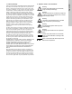
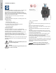
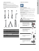
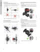
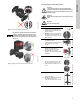
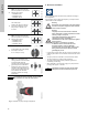
Table Of Contents
- English (US)
- 1. Limited warranty
- 2. Symbols used in this document
- 3. General information
- 4. Mechanical installation
- 5. Electrical installation
- 5.1 Supply voltage
- 5.2 Connection to the power supply (models 40-XX, 50-XX, 65-XX, 80-XX, 100-XX)
- 5.3 Connection to the power supply (models 32-XX)
- 5.4 Connection diagram
- 5.5 Input/output communication
- 5.6 Analog input for external sensor
- 5.7 Electrical connection for external sensor
- 5.8 Priority of settings
- 6. First start-up
- 7. Settings
- 8. Menu overview
- 9. Control panel
- 10. Menu structure
- 11. "Home" menu
- 12. "Status" menu
- 13. "Settings" menu
- 14. "Assist" menu
- 15. Selection of control mode
- 16. Fault finding
- 17. Sensor
- 18. Accessories
- 19. Technical data
- 20. Disposal

9
English (US)
Fig. 11 Incorrectly centered sealing system
Fig. 12 Fitting the pump head to the pump housing
4.5 Changing the control box position
TM05 6651 5012
Caution
Observe the position of the clamp before the
clamp is tightened. Incorrect position of the
clamp will cause leakage from the pump and
damage the hydraulic parts in the pump head.
See fig. 12.
TM05 5837 4112
Warning
The warning symbol on the clamp holding the
pump head and pump housing together indicates
that there is a risk of personal injury. See specific
warnings below.
Warning
When loosening the clamp, do not drop the pump
head.
Warning
Risk of escaping vapor.
Step Action Illustration
1
Loosen the screw in the clamp
holding the pump head and pump
housing together.
Warning: If the screw is loosened
too much, the pump head will be
completely disconnected from the
pump housing.
TM05 2867 0612
2
Carefully rotate the pump head to
the desired position.
If the pump head is stuck, loosen it
with a light blow of a rubber
mallet.
TM05 2868 0612
3
Position the control box in
horizontal position so that the
Grundfos logo is in vertical
position. The motor shaft must be
horizontal.
TM05 2869 0612
4
Due to the drain hole in the stator
housing, position the gap of the
clamp as shown in step 4a, 4b, 4c
or 4d.
TM05 2870 0612
4a
Single-head pump.
Position the clamp so that the gap
points towards the arrow.
It can be in position 3 or 9 o'clock.
TM05 2918 0612 - TM05 2871 0612