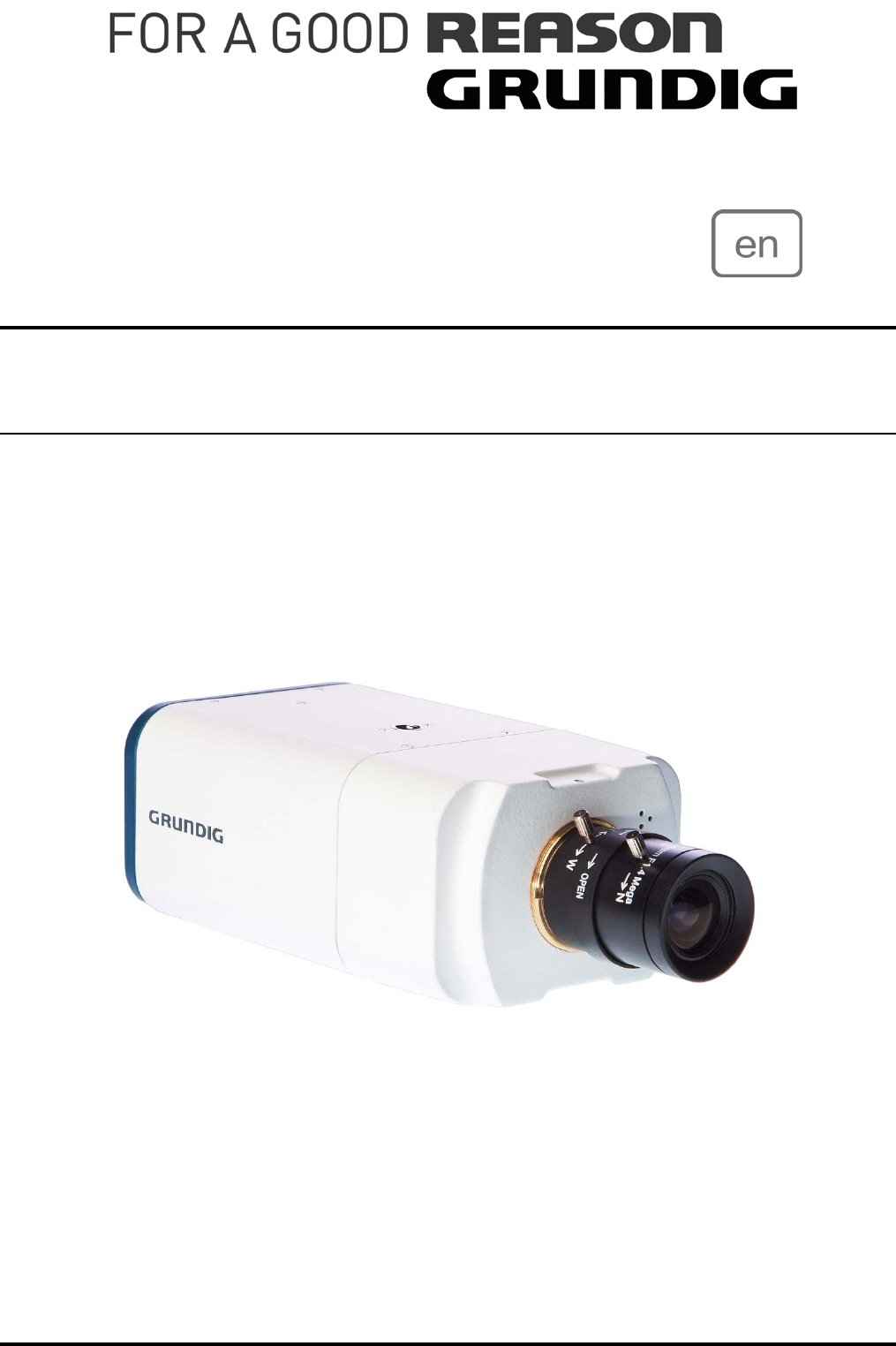
Owner´s Manual IP Cameras & Domes GCI-H0503B 720P HD IP Col/B&W Camera WDR Low Light GCI-H0602B 720P HD IP Colour Camera GCI-K0503B 1080P Full HD IP Col/B&W Camera GCI-K0503B.11.1.23.12.
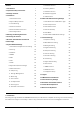
Content: 17. View Parameters 50 1. Introduction 1 18. Factory Default 50 2. Important Safety Instructions 2 19. Software Version 51 3. Package Contents 2 20. Software Upgrade 52 4. Installation 3 21. Maintenance 54 1. Camera Overview 3 2. System Requirements 3 3. Lens Mounting 4 4. Power Connection 4 5. Ethernet Cable Connection 4 6. Alarm Application 5 5. Deleting the Existing DC Viewer 5 6. Accessing the Camera 7 7. Browser-based Viewer Introduction 12 8.
In addition to MJPEG real time streaming, this IP Camera develops a superior H.264 main profile codec to smoothly transfer High Definition surveillance data through the Internet without distortion. Attributing to the IP Camera’s flexible platform, the camera can be applied in various installation locations including shops, stores, banks, parking lots, factories and building surveillance.
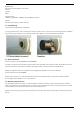
4. Installation Do not install in a location subject to high temperature (over 50°C), low temperature (below -10°C), or high humidity. Doing so may cause fire or electric shock. Keep out of direct sunlight and heat radiation sources. It may cause fire. Avoid aiming the camera directly towards extremely bright objects such as sun, as this may damage the CCD image sensor. Do not install the unit in humid, dusty, or sooty locations. Doing so may cause fire or electric shock.
Web Browser : Microsoft Internet Explorer 6.0 or later Firefox Chrome Safari Network Card : 10Base-T (10 Mbps) or 100Base-TX (100 Mbps) operation Viewer : ActiveX control plug-in for Microsoft IE 4.3. Lens Mounting Lens Mounting: C/CS Mount Lens Model: If using a C-Mount lens, after removing the camera’s plastic cover, users need to mount the C/CS mount adapter to the camera. Then attach the lens onto the C/CS mount adapter, as the illustrations show below. 4.4.
Check the status of the link indicator and activity indicator LEDs; if the LEDs are unlit, please check LAN connection. Green Link Light indicates good network connection. Orange Activity Light flashes for network activity indication. 4.6. Alarm Application The camera equips one alarm input and one relay output for alarm application. Refer to alarm pin definition below to connect alarm devices to the IP Camera if needed. PIN 1. Output+ PIN 2. OutputPIN 3. Input+ PIN 4. Input5.
Deleting Temporary Internet Files : To improve the browser performance, it is suggested to clean up all the files in the Temporary Internet Files. The procedure is as follows: STEP 1: Click on the “Tools” tab and select the option “Internet Options”. STEP 2: Click on “Delete”, then tap the “Delete Files” in the “Temporary Internet files” section.
The pop-up window for confirmation will come out as shown below. Click “OK” to start deleting the files. 6. Accessing the Camera For initial access to the IP Camera, users can search the camera through the installer program: GRUNDIG Finder.exe, which can be found in the “GRUNDIG Finder” folder on the supplied CD. GRUNDIG Finder Software Setup : Step 1: Double-click on the program GRUNDIG Finder.exe (see the icon below); its window will appear as shown below. Then click the “Find Device” button.
Step 2: The security alert window will pop up. Click “Unblock” to continue. Device Search : Step 3: Click “Find Device” again, and all the IP devices found will be listed on the page, as shown in the picture below. The IP Camera’s default IP address is: 192.168.1.1. Step 4: Double-click or right-click and select “Browse” to access the camera directly via web browser.
Step 5: Then the dialogue box for entering the default username and password (as shown below) will appear for logging in to the IP Dome Camera. The default login ID and password for the Administrator are: Login ID: admin Password: 1234 NOTE: ID and password are case sensitive. It is strongly advised that administrator’s password be altered for security concerns. Refer to section 9.2. Security for further details.
Step 2: The “Network Setup” page will come out. Select “DHCP,” and press the “Apply” button down the page. Step 3: Click “OK” on the Note of setting change. Wait for one minute to re-search the IP Camera. Step 4: Click the “Find Device” button to search all the devices. Then select the IP Camera with the correct MAC address. Double-click on the IP Camera, and the login window will come out. Step 5: Enter User name and Password to access the IP Camera.
The Information Bar (just below the URL bar) may come out and ask for permission to install the ActiveX Control for displaying video in browser (see the picture below). Right-click on the Information Bar and select “Install ActiveX Control…” to allow the installation. Then the security warning window will pop up. Click “Install” to carry on software installation. Click “Finish” to close the DC Viewer window when download is finished. For the detailed software download procedure, please refer to chapter 10.
7. Browser-based Viewer Introduction The picture below shows the Home page of the IP Camera’s viewer window. There are five tabs: Home, System, Streaming, Camera and Logout on the top panel. Home : Users can monitor the live video of the targeted area. System setting : The administrator can set host name, system time, root password, network related settings, etc. Further details will be interpreted in chapter 9. System Related Settings. Camera setting : Users can adjust various camera parameters.
8. Home Page In the Home page, there are several function buttons right down the displayed image. NOTE: Please note that the function buttons will vary depending on the camera model. Display Mode (Screen Size Adjustment) : Image display size can be adjusted to x1/2 and full screen. Digital Zoom Control : In the full screen mode, users can implement digital PTZ by rotating the mouse wheel (for zoom in/out), and drag the mouse into any direction.
Recording button (on/off) : Press the button and the recordings from the Live View will be saved to the location specified in the “File Location” (snapshot) page. The default storage location for the recording is: C:/. See section 7.3.13 File Location for further details. Multiple Languages Support : Multiple languages are supported for the viewer window interface. 9. System Related Settings The picture below shows all categories under the “System” tab.
9.1. Host Name and System Time Setting Press the first category: in the left column; the page is shown below. Host Name : The name is for camera identification. If alarm function (see section 9.8. Application) is enabled and is set to send an alarm message by Mail/FTP, the host name entered here will display in the alarm message. Time Zone : Select the time zone you are in from the drop-down menu.
: Click the tab under the category and the page is shown as the picture below. NOTE: The following characters are valid: A-Z, a-z, 0-9, !#$%&’-.@^_~. Admin Password : Change the administrator’s password by putting in the new password in both text boxes. The input characters/numbers will be displayed as dots for security purposes. After clicking , the web browser will ask the Administrator for the new password for access. The maximum length of the password is 14 digits.
NOTE: It is required to enter the User password and to select the function open to the user. When finished, click to modify the account authority.
: allows secure connections between the IP Camera and the web browser using the or the , which prevent camera settings or Username/Password info from snooping. It is required to install a self-signed certificate or a CA-signed certificate for implementing . Click the tab, and the HTTPS setting page is shown as the figure below. To use HTTPS on the IP Camera, a HTTPS certificate must be installed.
Create Self-signed Certificate : Before a CA-issued certificate is obtained, users can create and install a self-signed certificate first. Click the button under “Create self-signed certificate” and provide the requested information to install a self-signed certificate for the IP Camera. Please refer to the last part of this section: Provide the Certificate Information for more details.
Create Certificate Request : Click the “Create Certificate Request” button to create and submit a certificate request in order to obtain a signed certificate from CA. Provide the requested information in the Create Dialog. Please refer to the following Provide the Certificate Information for more details. When the request is complete, the subject of the Created Request will be shown in the field. Click “Properties” below the Subject field, copy the PEM-formatted request and send it to your selected CA.
When the signed certificate is returned, install it by uploading the signed certificate.
- Country: Enter a 2-letter combination code to indicate the country the certificate will be used in. For instance, type in “US” to indicate the United States. - State or province: Enter the local administrative region. - Locality: Enter other geographical information. - Organization: Enter the name of the organization to which the entity identified in “Common Name” belongs. - Organization Unit: Enter the name of the organizational unit to which the entity identified in “Common Name” belongs.
: When using the IP filter, access to the IP Camera can be restricted by denying/allowing specific IP addresses. General : - Enable IP Filter: Check the box to enable the IP Filter function. Once enabled, the listed IP addresses (IPv4) will be allowed/denied access to the IP Camera. Select “Allow” or “Deny” from the drop-down list and click the button to determine the IP Filter behaviour.
: The IP Camera is allowed to access a network protected by 802.1X/EAPOL (Extensible Authentication Protocol over LAN). Users need to contact the network administrator to receive certificates, user IDs and passwords. CA Certificate : The CA certificate is created by the Certification Authority for the purpose of validating itself. Upload the certificate for checking the server’s identity.
9.3. Network Click the category: , there will be a drop-down menu with tabs including , , , and . : Users can choose to connect to the IP Camera through a fixed or dynamic (DHCP) IP address. The IP Camera also provides PPPoE (Point-to-Point Protocol over Ethernet) support for users who connect to the network via PPPoE.
Get IP address automatically (DHCP): The camera’s default setting is “Use fixed IP address”. Please refer to the previous section 6. Accessing the Camera for login with the default IP address. If “Get IP address automatically” is selected, after the IP Camera restarts, users can search the IP address through the installer program “GRUNDIG Finder.exe”, which can be found in the “GRUNDIG Finder” folder on the supplied CD.
- Primary DNS: Primary DNS is the primary domain name server that translates hostnames into IP addresses. - Secondary DNS: Secondary DNS is a secondary domain name server that backups the primary DNS. Use PPPoE : For the PPPoE users, enter the PPPoE Username and Password into the fields, and click on the “Save” button to complete the setting. Advanced : - Web Server port: The default web server port is 80.
(Quality of Service) : QoS allows providing differentiated service levels for different types of traffic packets, which guarantees delivery of priority services especially when network congestion occurs. Adapting the Differentiated Services (DiffServ) model, traffic flows are classified and marked with DSCP (DiffServ Codepoint) values, and thus receive the corresponding forwarding treatment from DiffServ capable routers. DSCP Settings : The DSCP value range is from 0 to 63.
(Simple Network Management Protocol) : With Simple Network Management Protocol (SNMP) support, the IP Camera can be monitored and managed remotely by the network management system. SNMP v1/v2 : - Enable SNMP: Select the version of SNMP to use by checking the box. - Read Community: Specify the community name which has read-only access to all supported SNMP objects. The default value is “public”.
: UPnP Setting : - Enable UPnP: When the UPnP is enabled, whenever the IP Camera is presented to the LAN, the icon of the connected IP Cameras will appear in My Network Places to allow for direct access as shown below.
NOTE: To enable this function, please make sure the UPnP component is installed on your computer. Please refer to chapter 11. Install UPnP Components for UPnP component installation procedure. - Enable UPnP port forwarding: When the UPnP port forwarding is enabled, the IP Camera is allowed to open the web server port on the router automatically. NOTE: To enable this function, please make sure that your router supports UPnP and is activated. - Friendly name: Set the name for the IP Camera for identity.
9.4. DDNS The Dynamic Domain Name System (DDNS) allows a host name to be constantly synchronized with a dynamic IP address. In other words, it allows those using a dynamic IP address to be associated to a static domain name so that others can connect to it through this name. Enable DDNS : Check the item to enable DDNS. Provider : Select one DDNS host from the provider list. Host name : Enter the registered domain name in the field.
9.5. Mail The Administrator can send an e-mail via Simple Mail Transfer Protocol (SMTP) when a motion is detected. SMTP is a protocol for sending e-mail messages between servers. SMTP is a relatively simple, text-based protocol, where one or more recipients of a message are specified and to whom the message text is transferred. The configuration page is shown below: Two sets of SMTP can be configured. Each set includes SMTP Server, Account Name, Password and E-mail Address settings.
9.6. FTP The Administrator can set to sending alarm messages to a specific File Transfer Protocol (FTP) site when motion is detected. Users can assign an alarm message to up to two FTP sites. The FTP setting page is shown below. Enter the FTP details, which include server, server port, user name, password and remote folder, in the fields. Press “Save” when finished.
9.7. HTTP A HTTP Notification server can listen for notification messages from IP Cameras by triggered events. The HTTP setting page is shown below. Enter the HTTP details, which include server, user name, and password in the fields. triggered and notifications can be sent to the specified server. Click “Save” when finished. Please refer to: 9.8. Application: Send HTTP notification / 9.9. Motion Detection for HTTP Notification settings. 9.8.
Alarm Switch : The Administrator can enable or disable the alarm function. Alarm Type : Select an alarm type, “Normal close” or “Normal open”, that corresponds with the alarm application. Alarm Output : Define alarm output signal as “high” or “low” for the normal alarm output status according to the current alarm application. Triggered Action (Multi-option) : The Administrator can specify alarm actions that will take place when motion is detected.
- Upload Image by FTP: Select this item, and the Administrator can assign a FTP site and configure various parameters as shown in the figure below. When the alarm is triggered, event images will be uploaded to the appointed FTP site. - Record Stream to SD Card: Select the item, and the alarm-triggered recording will be saved on your Micro SD card. NOTE: Please make sure the local recording (with Micro SD/ SDHC card) is activated so that this function can be implemented. See section 7.3.
- Upload Image by E-Mail: Select this item, and the Administrator can assign an e-mail address and configure various parameters as shown in the figure below. When the alarm is triggered, event images will be sent to the appointed e-mail address. NOTE: Make sure SMTP or FTP configuration has been completed. See section 9.5. Mail and 9.6. FTP for further details.
- Send HTTP notification: Check this item, select the destination HTTP address, and specify the parameters for event notifications when is triggered. When an alarm is triggered, the notification can be send to the specified HTTP server. File Name : Enter a file name into the blank box, e.g. image.jpg. The uploaded image’s file name format can be set in this section. Please select the one that meets your requirements. - Add date/time suffix: File name: imageYYMMDD_HHNNSS_XX.
9.9. Motion Detection The Motion Detection function allows detecting suspicious motion and triggering alarms when motion volume in the detected area reaches/exceeds the determined sensitivity threshold value. In the Motion Detection setting page is a frame (Motion Detection Window) displayed in the Live View Pane. The Motion Detection Window is for defining the motion detection area.
When motion is detected, the signals will be displayed in the Motion window as shown below: Detailed settings of Motion Detection are described as follows: Motion Detection : You will be able to turn on/off Motion Detection in System section. Default setting is Off. Motion Detection Setting : Users can adjust various parameters of Motion Detection in this section. - Sampling pixel interval [1-100]: The default value is 10, which means the system will take one sampling pixel for every 10 pixel.
- Upload Image by FTP: Select this item, and the Administrator can assign a FTP site and configure various parameters as shown in the picture below. When a motion is detected, event images will be uploaded to the appointed FTP site. - Upload Image by E-Mail: Select this item, and the Administrator can assign an e-mail address and configure various parameters as shown in the picture below. When a motion is detected, event images will be sent to the appointed e-mail address.
9.10. Tampering The Tampering Alarm function helps the IP Camera against tampering such as deliberate redirection, blocking, spray paint, and lens covering, etc. through video analysis and reaction to such events by sending out notifications or uploading snapshots to the specified destination(s). Detection of camera tampering is achieved by measuring the differences between the older frames of video (which are stored in buffers) and more recent frames.
- Upload Image by FTP: Select this item, and the Administrator can assign a FTP site and configure various parameters as shown in the figure below. When tampering is detected, event images will be uploaded to the appointed FTP site. NOTE: The capital letter A/M/R appearing in the very beginning of a name denotes the sort of the recording: A stands for Alarm; M stands for Motion; R stands for regular recording.
NOTE: Please format the Micro SD/SDHC card when using it for the first time. Formatting will also be required when a memory card has already been used on one camera and was later transferred to another camera with a different software platform. Device Information : When users insert the Micro SD/SDHC card, the card information such as the memory capacity and status will be shown in the Device Information section.
- Sort: Press the “Sort” button, and the files in the Recording list will be listed in name and date order. - Download: To open/download a video clip, select the file first, and then press the “download” button below the Recording list field. The selected file window will pop up as shown below. Click on the AVI file to directly play the video in the player or download it to a specified location. 9.12.
Terminating Micro SD/SDHC Card Recording : Select “Disable” to terminate the recording function. 9.13. File Location Users can specify a storage location for the snapshots and the live video recording. The default setting is: C:\. Once the setting is confirmed, press “Save,” and all the snapshots and recordings will be saved in the designate location. NOTE: Please make sure the selected file path contains valid characters such as letters and numbers.
9.14. Iris Adjustment For users who use an auto-iris lens, when it is required to undertake an iris adjustment, please refer to the iris adjustment procedure in the sub-menu Iris Adjustment to adjust the iris. 9.15. View Log File Click on the link to view the system log file. The content of this file provides useful information about configuration and connections after system boot-up.
9.16. View User Information The Administrator can view each user’s login information and their privileges (see 7.3.2 Security). View User Login Information : All the users in the network will be listed in the “User Information” zone, as shown below.
View User Privilege : If you press “Get user privacy” at the bottom of the page, the Administrator will be able to view each user’s privileges. As the picture above shows: User: 1:1:0:1 1:1:0:1 = I/O access : Camera control : Talk : Listen (see 7.3.2 Security) This denotes that the user has been granted the privileges of I/O access, Camera control and Listen.
9.17. View Parameters Click on this item to view the entire system’s parameter setting. 9.18. Factory Default The factory default setting page is shown below. Follow the instructions to reset the IP Camera to factory default setting if needed.
Set Default : Click on the “Set Default” button to recall the factory default settings. Then the system will restart in 30 seconds. Reboot : Click on the “Reboot” button, and the system will restart without changing the current settings. 9.19. Software Version The current software version is displayed in the software version page, which is shown in the picture below.
9.20. Software Upgrade Software upgrade can be carried out on the “Software Upgrade” page, as shown below. NOTE: Make sure the upgrade software file is available before carrying out the software upgrade. The procedure of a software upgrade is as follows: Step 1: Click “Browse” and select the binary file to be uploaded, e.g. Userland.jffs2. NOTE: Do not change the upgrade file name, or the system will fail to find the file.
9.21. Maintenance Users can export configuration files to a specified location and retrieve data by uploading an existing configuration file to the IP Camera. Export: Users can save the system settings by exporting the configuration file (.bin) to a specified location for future use. Press the “Export” button, and the popup File Download window will come up as shown below. Click “Save” and specify a desired location for saving the configuration file.
10. Video and Audio Streaming Settings Press the tab ”Streaming” on the top of the page, and the configurable video and audio items will display in the left column. In Streaming, the Administrator can configure specific video resolution, video compression mode, video protocol, audio transmission mode, etc. Further details of these settings will be specified in the following sections. 10.1. Video Resolution and Rotation Type The video setting page is shown below: Video Format : Resolution for MJPEG & H.
Text Overlay Settings : Users can select the items to display data including date/time/text on the live video pane. The maximum length of the string is 20 alphanumeric characters. Click “Save” to confirm the Text Overlay setting. Video Rotation Type : Users can change the video display type if necessary. Selectable video rotate types include Normal video, Flip video, Mirror video and 180 degree rotation. Differences among these types are illustrated below.
10.2. Video Compression Users can specify the values for MJPEG/H.264 compression mode in the video compression page (see the picture below), depending on the application. MJPEG Q (Quality) factor : Higher value implies higher bit rates and a higher visual quality. The default setting of MJPEG Q factor is 35; the setting range is from 1 to 70. H.264-1 / H.264-2 bit rate : The default setting of H.264-1 / H.264-2 is 4096 kbps; the setting range is from 64 to 8192 kbps.
CBR Mode Setting : The CBR (Constant Bit Rate) mode can become the preferred bit rate mode if the bandwidth available is limited. It is important to take into account the image quality when you choose to use CBR mode. 10.3. Video OCX Protocol In the Video OCX protocol setting page, users can select RTP over UDP, RTP over TCP, RTSP over HTTP or MJPEG over HTTP, for streaming media over the network. In the case of multicast networking, users can select the Multicast mode.
Video OCX protocol setting options include: - RTP over UDP / RTP over RTSP (TCP) / RTSP over HTTP / MJPEG over HTTP (Select a mode according to your data delivery requirements.) - Multicast Mode: Enter all required data, including multicast IP address, H.264 video port, MJPEG video port, audio port and TTL into each blank. Click “Save” to confirm the setting. 10.4. Video Frame Skip Video frame skipping is for saving bandwidth if necessary. The setting page is shown below.
10.5. Video Mask There are up to five video masks which can be set by the users. Active Mask Function : - Add a Mask: Check a Video Mask checkbox, and a red frame will come out in the Live Video pane at the right side. Use the mouse to drag and drop in order to adjust the mask’s size and place it on the target zone. NOTE: It is suggested to set the Video Mask twice as big as the object.
10.6. Audio Mode and Bit Rate Settings The audio setting page is shown below. In the Audio page, the Administrator can select one transmission mode and audio bit rate. Transmission Mode : - Full-Duplex (Talk and Listen simultaneously): In the Full-Duplex mode, the local and remote sites can communicate with each other simultaneously, i.e. both sites can speak and be heard at the same time.
11. Camera Settings The picture below is the camera configuration page. Details of each parameter setting are described in the following subsections. NOTE: Camera settings and function buttons may vary depending on the camera model. 11.1. Exposure Setting The Exposure pull-down menu is as follows: The exposure is the amount of light received by the image sensor and is determined by the width of lens diaphragm opening, the amount of exposure by the sensor (shutter speed) and other exposure parameters.
NOTE: The minimum shutter speed will vary depending on the setting in Full Auto Mode. Fixed Shutter Mode : In this mode, a fixed shutter speed can be selected from the dropdown menu. The shutter speed range is from 1/10000 to 1 (1/1.5) sec. with 19 (18) options. Users can choose a suitable shutter speed according to the environmental illumination. 11.2.
11.4. Brightness Setting Users can adjust the image’s brightness by adjusting the item. To increase video brightness, select a bigger number. Press < √ > to confirm the new setting. 11.5. Sharpness Setting Sharpness Setting Increasing the sharpness level can make the image look sharper; it especially enhances the object’s edges. Press < √ > to confirm the new setting. 11.6. Contrast Setting The camera image contrast level is adjustable; please choose from a range of -6 to +19.
11.11. WDR Function The Wide Dynamic Range (WDR) function* is for solving high contrast or changing light issues so that it improves the video display. The WDR is adjustable from level 1 to 4. A higher level of WDR represents a wider dynamic range, so that the IP Camera can catch a greater scale of brightness. Press < √ > to confirm the new setting. * The WDR function is only available for GCI-H0503B. 11.12.
For further information on CMS software, please refer to the supplied CD. NOTE: The free bundle CMS is a function-limited software. For additional features, please purchase a licensed CMS. 14. Internet Security Settings If ActiveX control installation is blocked, please either set Internet security level to default or change ActiveX controls and plug-in settings. Internet Security Level : Default Step 1: Start the Internet Explorer (IE). Step 2: Select from the main menu of the browser.
Step 3: Click the tab, and select . Step 4: Down the page, press “Default Level” (see the picture above) and click “OK” to confirm the setting. Close the browser window, and open a new one later when accessing the IP Camera. ActiveX Controls and Plug-in Settings : Step 1~3: Refer to the previous section above. Step 4: Down the page, press “Custom Level” (see the picture below) to change ActiveX controls and plug-in settings.
The Security Settings screen is displayed as shown below: Step 5: Under “ActiveX controls and plug-ins”, set ALL items (as listed below) to or . ActiveX controls and plug-in settings: 1. Automatic prompting for ActiveX controls 2. Binary and script behaviours 3. Download signed ActiveX controls 4. Download using ActiveX controls 5. Initialize and script ActiveX not marked as safe 6. Run ActiveX controls and plug-ins 7.
15. DC Viewer Download Procedure The procedure of DC Viewer software download is specified as follows: Step 1: In the DC Viewer installation page, click “Next” for starting the installation. Step 2: Setup starts. Please wait for a while until the loading bar runs out.
Step 3: Click “Finish” to close the DC Viewer installation page. Then, the IP Camera’s Home page will display as follows: NOTE: Please note that the function buttons may vary depending on the camera model.
16. Install UPnP Components Please follow the instructions below to install UPnP components. Step 1: Go to “Start”, click on “Control Panel”, and then double-click on “Add or Remove Programs”. Step 2: Click on “Add/Remove Windows Components” in the Add or Remove Programs page.
Step 3: Select “Networking Services” from the Components list in the Windows Components Wizard window, and then click “Details”. Step 4: Select “UPnP User Interface” in the Networking Services’ subcomponents list and then click “OK”. Step 5: Click “Next” in the Windows Components Wizard page.
Step 6: Click “Finish” to complete the installation. 17. Back Focus Adjustment When to adjust the back focus: Back Focus refers to the distance from the rear lens element to the camera focal plane. In most cases, it is required to adjust the back focus only when the camera’s lens cannot hold focus throughout its zoom range. Requirements: Tools required when carrying out back focus adjustment include: 1.Back focus adjuster (in the IP Camera’s package) 2.
Specifications GCI-H0503B Image Sensor 1/3" CCD, 1.3 megapixel Col/B&W On/Off/Auto, IR-cut filter removable (ICR) Pixels - total 1280 (H) x 960 (V) Sensitivity 0.03 lux @ F1.2 (Colour) / 0.001 lux @ F1.
Sensitivity 0.2 lux @ F1.2 (Colour) / 0.02 lux @ F1.2 (B&W) Video Resolution Full HD 1920 x 1080 (25 fps), 720P 1280 X 720 (2x25 fps) Supply Voltage 12 VDC / 24 VAC / PoE IEEE 802.3af Power Consumption 5.5 W Weight 0.
EC Declaration of Conformity GCI-H0503B 720P HD IP Col/B&W Camera WDR Low Light GCI-H0602B 720P HD IP Colour Camera GCI-K0503B 1080P Full HD IP Col/B&W Camera It is hereby certified that the products meet the standards in the following relevant provisions: EC EMC Directive 2004/108/EC Low Voltage Directive 2006/95/EC Applied harmonized standards and technical specifications: EN 55022 Class A (2006 + A1: 2007) EN 61000-3-2 (2006) EN 61000-3-3 (2008) EN 61000-3-3 (1995 + A1: 2001 + A2: 2005) EN 55024 (1