Owner's Manual Digital Recording Systems GRI-K1104A GRI-K2208A GRI-K4416A GRI-K4416A.81.1.14.12.2012 © ASP AG 4-Ch Full HD Standalone H.264 NVR 8-Ch Full HD Standalone H.264 NVR 16-Ch Full HD Standalone H.
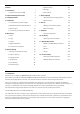
7. System Setup 55 1 8. Storage 61 1. Key Features of your NVR 2 9. Event Setup 64 2. Important Safety Instructions 3 3. Package Contents 4 1. Starting the Record Setup Menu 75 4. Installation 5 2. Record Setup 75 Content: 1. Introduction 1. Connections and Control Keys 5 2. HDD Specifications & Replacement 8 3. Basic Layout 10 4. Connecting To An External Device 10 5. Monitoring 7. Record Setting 8. Search 83 1. Moving To The Search Menu 83 2. Search Settings 83 9.
- Malfunctions due to negligence by the user - Deliberate disassembly and replacement by the user - Connection of a power source other than a properly rated power source - Malfunctions caused by natural disasters (fire, flood, tidal wave, etc.) - Replacement of expendable parts (HDD, FAN, etc.) - Malfunction caused by using an unrecommended HDD - Malfunction due to HDD failure and not due to a problem in the NVR - The warranty period for the Fan is one year after purchase.
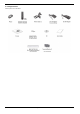
- 1080p Full HD GUI 2. Important Safety Instructions GRUNDIG shall not have any responsibility for any accident or damage that may incur during the use of this product. For your safety, we provide a few instructions about installation, manipulation, cleaning, assembly/disassembly of the product as below. So please read carefully and comply with the instructions. Before installation : Comply with the following instructions to prevent a fire, explosion, system failure or electric shock.
3.
4. Installation 4.1.
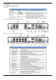
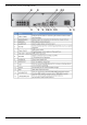
Rear View of the recorder model GRI-K4416A: English 6
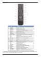
Remote Control: The remote control will only be active if the remote control ID matches with that specified on the NVR. If multiple NVRs are installed on one place and you have just a single remote control, use the ID button to set the remote control ID. Only the ID-matching NVR can be controlled.
1. Under - in the System Setup menu, set the and press . Select between 00 and 99. For more details, please refer to . The remote control will be active only if the remote control ID matches the system ID of the NVR. 2. Press the [ID] button on the remote control. The default remote control ID is 00. 3. Use the number buttons to provide a two-digit ID. If you want to enter 01, for instance, enter the number 0 and 1 in sequence.
3. Hold the middle of the HDD bracket's handle with the index finger and pull it forward while sustaining the bracket handle with your thumb and middle finger as shown in the illustration below. 4. Once the HDD bracket is separated from the main unit, remove the 4 screws on both ends of the HDD bracket to separate the HDD from the bracket. 5. Install a new HDD and fasten the 4 screws back to both ends of the bracket to fix it. NOTE: When installing the HDD, make sure to install it in the correct direction.
4.3. Basic Layout Basic Layout: 4.3.1. Precautions To secure the recording stability from an overloaded network traffic, and to protect the NVR from hacking attempts or DoS (Denial of Service) attacks, only the direct cable connection between camera and NVR is allowed. Using a hub is only allowed for extending a single channel to an extended transfer range of 100m each. Any access from an outside PC to the IP camera will be strictly prohibited for the purpose of secure operation.
- Do not insert multiple devices into a single power socket. Otherwise, it may cause a power overload. - For a stable power supply, this product provides two separate adapters and two corresponding AC cords by factory default. Make sure all cables are connected properly. - Make sure the power connector and the cable are connected tightly and are not loose.
4.4.3. Connecting the Camera Guidelines for this connection: - If the IP camera provides the Alarm I/O port or Audio I/O port, you can make the alarm or audio connection. For more details, please refer to the user manual of the IP camera. - The Ethernet connection is effective within 100 meters in distance. Beyond that, you may encounter a data loss or failure to connect to the camera.
Additional camera connection for GRI-K4416A: Connect IP cameras to the [CAM9] ~ [CAM16] ports of the hub, and connect the [LAN (DOWNLINK)] port and the hub’s [NVR] port with an Ethernet cable to establish the connections for the channels/cameras 9~16. If the distance between the NVR and IP camera is more than 100m: You may extend the transfer range by connecting a switching hub or PoE device between the Ethernet port of the NVR and of the IP camera if the desired transfer distance is longer than 100m.
4.4.4. Alarm I/O Connection Alarm Connection for GRI-K1104A and GRI-K2208A: Connecting the alarm input signal : Connect the signal line of an alarm input device such as a sensor to the rear [ALARM IN] port. 1. While pressing and holding the [A1] or [A2] port button in the rear bottom of the NVR, insert the alarm signal cable into the hole under the button. 2. Insert the grounding wire into the [GND] port. 3.
2. Insert one end of the alarm signal cable through the [A1] or [A2] terminal hole below the screw hole, and then fasten the screw. 3. Insert the ground signal wire into the hole of the [GND] port (shown also below the screw), and tighten the screw. 4. To ensure a secure connection, tighten the screw and pull out the wire to check if it is not pulled out. To remove the wire, loosen the screw and pull it out.
RS-485 Connection : Connect the keyboard controller. You can connect a text-in device such as POS or ATM. After connecting the control device, be sure to match the connection settings between the NVR and the device. Make the communication settings in the submenu (See chapter 6.7.4. Control Device). 1. Use the signal line to make the connection between [D+] of the rear NVR and [D+] of the keyboard controller. 2.
4.4.9. Network Connection PC connection in the local network : You can connect an NVR to a PC in the same network and control or edit it on the PC monitor. 1. Connect the [WAN(UPLINK)] port in the rear panel of the NVR to the router or hub. 2. Connect the local PC to the router or hub. 3. Enter the address in the address bar (web browser) of the local PC or of the dedicated software program in the format of “http://IP address:web service port” (Ex : http://192.168.0.23:8080).
PC connection from a remote network : You can connect an NVR to a PC or mobile device in the same remote network and control or edit it on the monitor of the PC or mobile device. 1. Connect the [WAN(UPLINK)] port in the rear panel to the router. 2. Connect the [WAN(UPLINK)] port of the router directly to the fixed IP LAN cable, or connect it to the ADSL modem. 3.
5. Monitoring 5.1. Start 1. For GRI-K1104A and GRI-K2208A: Connect the adapter to the 48V PoE power input port in the rear panel of the NVR. Connect the adaptor to the 12V power input port in the rear panel of the NVR. For GRI-K4416A: Connect the adaptor to the power input port in the rear panel of NVR. ATTENTION: Make the connection when the power is not applied yet. 2. Turn on the power switch on the rear panel of the NVR. First you hear a beep and the LEDs light up.
5.3. Logout To prevent unauthorised access, it is recommended to log out when you leave the screen. Hover the cursor near the bottom of the screen to display the menu. 1. In the monitoring screen, click
5.4. System Shutdown 1. In the monitoring screen, click
English 22
5.5.1. Video Window Icons used in the video window : 5.5.2.
5.5.3. Status Bar Press the [▼] button on the remote control, or place the mouse cursor in the lower area of the screen to display the status bar. 5.5.4. Timeline Press the [▶] button on the remote control or move the mouse cursor to the right of the screen to display the timeline. Double-click the timeline to move to the video screen. Drag the cursor on the timeline to mark a certain area in which you want to make the backup or the event search.
5.5.5. Using the Status Bar in Live Mode Selecting a split mode : Click a desired split mode from 1, 4, 9, 16, 6 and 8 split screen. Or press the [DISPLAY] button on the remote control until a desired split mode is displayed. NOTE: The 4CH NVR model GRI-K1104A only supports 1- and 4-split screen modes. The 8CH NVR model GRIK2208A only supports 1-, 4-, 9-, 6- and 8-split screen modes.
Pan/Tilt Control : Use the mouse to rotate the PTZ camera in the directions Up/Down/Left/Right and Diagonal. You can control the Pan/Tilt with the [▲▼◄►] buttons of the remote control. Zoom / Focus Control : You can adjust the PTZ camera's zoom and focus. Click on the button to adjust the camera’s focus automatically. If the connected camera supports manual iris adjustment, you can adjust the iris setting.
> CH : Selects the PTZ camera connected to the NVR. > PRESET (No. / Name) : You can select the preset number and name. NOTE: Up to 255 presets can be selected for a PTZ camera, while up to 16 presets can be registered to one NVR. 2. Control the Camera’s PTZ while watching the video. Press the button to append the preset. > Click the shortcut icon to move to the corresponding PTZ (preset) position. > Click on the Delete icon to delete the corresponding preset.
3. Select a user-defined preset and register it. > DWELL : Sets the dwell time of 00 seconds before moving to the next preset location. NOTE: The function patrols between two preset positions at the specified speed and interval for backand-forth monitoring. 4. Select and click on the button. 5. Click on the button. 6. Select a user-defined preset and register it. > DWELL: Sets the dwell time of 00 seconds before moving to the next preset location.
Digital Zooming : You can enlarge the monitoring screen for a better view. Zooming will enlarge the video of the selected channel. If no channel is selected, channel 1 will be zoomed in. 1. Click on in the status bar or move the cursor to a desired channel and right-click on it to display the context menu. Select . You can also press the [ZOOM] button on the remote control. 2. Move to the zoom control screen.
How to check the event log : You can check the log of the events that occurred. 1. Click on the symbol (please refer to the picture) to display the “EVENT LOG” window. The log list is sorted with the latest one on top. 2. Double-click on a desired log to playback the event video in the playback screen. How to select an audio input channel : Select a channel from which the audio signal will be received. > CH : Produces the selected channel’s audio, regardless of the split screen mode.
How to select an audio output channel : You can select a camera outputting the voice signal from the microphone that is connected to the NVR. How to check the alarm status : You can check here the alarm status of each camera. Click on to close the window. How to check the network status : You can check here the network connection status. Click on to close the window. NOTE: For more information, please refer to Chapter 6.6.4. Network Status.
How to check the disk status : You can check here the storage space of the current disk and you can check also if there is any problem with the disk. Click on to close the window. NOTE: For more information, please refer to Chapter 6.8.1. Disk Information). Saving captured snapshots : You can capture the current video screen and save or export to a connected storage device. 1. Select a channel first, and right-click to open the pop-up menu.
2. Connect a storage device, and click on the button. To save the captured image onto the built-in HDD, press the button. NOTE: The saved image can be found under “Archiving > Reserved data management” and can then be backed up. 3. Enter the and the and press the or button. > A progress bar appears and indicates the progress of the export to a storage device. > BURN : The snapshot is stored in the connected USB storage device.
6. System Setting Please note that the OSD pictures shown in this manual refer mainly to the 8-channel NVR with the model name GRI-K2208A, therefore 8 frames/channels are mostly shown in the pictures. 6.1. Moving To The System Setup > How to use the mouse : > How to use the remote control (1) : > How to use the remote control (2) : 6.2. Camera Setting You can configure the camera settings in the NVR menu regarding the camera ID, image, hide/show, and motion.
6.2.1. Camera Title You can change the camera ID that is displayed on the screen like explained in the following: 1. From - , select . 2. Use the [▲▼◀▶/ENTER] buttons on the remote control or use the mouse to select a channel that you want to rename. Alternatively, simply double-click on the camera name to rename from the top left corner. NOTE: Allows input of up to 8 bytes of alphanumeric characters. 3.
6.2.2. Camera Setup Adjust the Image & Exposure settings for each camera according to your preference. 1. From - , select . 2. Use the [▲▼◀▶/ENTER] buttons on the remote control or use the mouse to set each option of the Image menu. ATTENTION: The camera setting items may differ depending on the camera model. IMAGE SETTINGS: - BRIGHTNESS: Adjust the brightness level of the camera between 0 and 100. - CONTRAST: Adjust the contrast level of the camera between 0 and 100.
3. Click on tab and configure the Exposure settings in detail for each camera as necessary. ATTENTION: The exposure setting items may differ depending on the camera model. 4. To apply the change, click in the bottom of the screen. EXPOSURE: - MODE: Select between manual and automatic configuration for the exposure settings. - BLC CONTROL: Activate or deactivate the backlight compensation control. In strong backlight situations this might improve the picture quality.
DIRECT ACCESS: In the direct configure tab you can activate the port forwarding of a dedicated camera. This will allow you to access the camera webinterface through the IP address of the NVR. Click on the button to activate the direct configure mode. To access the camera enter the IP address + the Webservice port of the NVR into your browser and enter the correct login data. The IP address and the Webservice port you can find under SYSTEM > NETWORK > IP SETUP.
6.2.3. Covert Setup You can set to hide the camera video so that a specific user or user group cannot view it. Set one or more channels that you want to hide from a specific user or user group. 1. From - , select . 2. Use the [▲▼◀▶/ENTER] buttons on the remote control or use the mouse to select one or several covert channels from a specific user group. > ADMIN, MANAGER, USER : If you set them to , the selected channels will be covert from the applicable user account.
6.2.4. Motion Sensor Set the motion sensor of the camera so that the NVR can detect a motion event. 1. From - , select . 2. Use the [▲▼◀▶/ENTER] buttons on the remote control or use the mouse to specify the use of each option item. > ACTIVATION : Turn the motion sensor on or off. > MOTION MARK : If you set it to , the video window will display the motion mark if a motion is detected. 3. To apply the change, click on in the bottom of the screen. 4.
1. Click on to move to the motion area setup screen. 2. If using the remote control, press the [ENTER] button to mark the current position. 3. Use the arrow buttons to move to a desired block and then press [ENTER]. The area setup will begin. Then, use the arrow buttons to specify the area. Alternatively, you can use the drag-and-drop method to specify or release the area by using the mouse. 4. If you select the specified area again, it will be released. 5.
- DAYTIME : Specify the time period that will be considered as daytime. - SENSITIVITY : Set the sensitivity level of the motion sensor to either Daytime or Nighttime: 1(Low) ~ 10(High) The higher the number is, the higher the sensitivity level becomes. - MINIMUM BLOCKS : Set the minimum number of blocks to Daytime or Nighttime if a motion is detected in several blocks in the motion sensor area: 1(High) ~ 10(Low) - The lower the number is, the higher the sensitivity level becomes.
1. From - , select . 2. Use the [▲▼◀▶/ENTER] buttons on the remote control or use the mouse to set each option of the OSD item. > CAMERA TITLE : Specify the display of the camera title on the screen. > RECORDING MODE ICON : Specify the display of the record mode icon on the screen. > AUDIO ICON : Specify the display of the audio icon on the screen. > STATUS BAR IN FULL SCREEN MODE : Select to show/ how to show or hide the status bar in full screen mode.
1. From - , select . 2. Use the [▲▼◀▶/ENTER] buttons on the remote control or use the mouse to set a sequence interval for auto mode, from 1 to 60 seconds. 3. To apply the change, click on in the bottom of the screen. 4. When done, press the [EXIT] button on the remote control or click in the lower screen. The confirmation message will appear and you will return to the previous menu. 6.3.3.
3. To apply the change, click on in the bottom of the screen. 4. When done, press the [EXIT] button on the remote control or click on in the lower screen. The confirmation message will appear and you will return to the previous menu. How to add a sequence : 1. Click on in the bottom of the screen. 2. When the "ADD" dialogue appears, enter a title using the virtual keyboard. 3. Enter the name of the sequence and click on . 4.
How to edit a sequence : 1. Select a sequence that you want to edit from the list. 2. The "EDIT" dialogue appears. 3. Use the [▲▼◀▶/ENTER] buttons on the remote control or use the mouse to edit the selected sequence. > SEQUENCE TITLE : Enter a new sequence name. > ACTIVATION : Specify the use of the sequence. > MODIFY : Change the settings of the sequence mode. > DELETE : Delete the selected sequence list. > CANCEL : Cancel the changes. 4. Pressing the button will display the Edit Sequence window.
6.4. Audio Setup You can configure the audio and the signal beeps. 6.4.1. Audio You can configure here the default audio channel and configure the network audio transmission. 1. From -
1. From -
1. From - , select . 2. Use the [▲▼◀▶/ENTER] buttons on the remote control or use the mouse to add a user account or select an item that you want to edit. 3. To apply the change, click on in the bottom of the screen. 4. When done, press the [EXIT] button on the remote control or click on in the lower screen. The confirmation message will appear and you will return to the previous menu. How to add a user account : 1. Click in the bottom of the screen.
3. When done, click on . The added user account will be listed. How to edit the user account information : 1. From the list of users, select a user account to edit and click next to it. 2. In the Edit window, make the necessary changes and click on . 3. To delete the user account, click on . NOTE: The account cannot be changed or edited. 6.5.2. Group Authority You can grant different user groups different permissions to a specific menu. 1.
> SEARCH : Set the permissions for the Search menu. > ARCHIVING : Set the permissions for the Backup menu. > SYSTEM SETUP : Set the permissions for the System Setup menu. > RECORD SETUP : Set the Access Permissions for the Record Setup menu. > EVENT ACTION CONTROL : Set the permissions to output the alarm or control the buzzer if an event such as an alarm occurs. > LISTEN TO AUDIO : Set the permission to listen to the audio. > MICROPHONE : Set the permission to speak through the microphone.
> IP ADDRESS : Provide the IP address. > GATEWAY : Provide the gateway address. > SUBNET MASK : Provide the subnet mask address. > 1ST DNS SERVER : Enter the address of the primary DNS server. > 2ND DNS SERVER : Enter the address of the secondary DNS server. > RTSP SERVICE PORT : Port number that the remote client receives the NVR video from. > WEB SERVER PORT : Port number used for connecting to the NVR with the web browser.
3. To apply the change, click on in the bottom of the screen. 4. When done, press the [EXIT] button on the remote control or click in the lower screen. The confirmation message will appear and you will return to the previous menu. 6.6.3. Email You can register and test an email address so that an email notification can be delivered at a specific interval or if an event occurs. 1. From - , select . 2.
Network Map : > IP ADDRESS : Indicates the internal IP address of the NVR. > MAC ADDRESS : Indicates the internal MAC address of the NVR. > DDNS ADDRESS : Indicates the internal DDNS address of the NVR. > RTSP SERVICE PORT : Indicates the network port of the video service. For remote service, the router must have set up the port forwarding. > WEB SERVICE PORT : Indicates the web service network port.
Detail Status : You can check the details of the cameras that are connected to each channel. Click on the 'Cogwheel' Button in the right area of the list to show the details. Click in the "IP CAMERA CONFIGURATION" window to reset the IP camera. When the IP camera settings are complete, click on . 6.7. System Setup You can configure the settings of date/time, system management, and keyboard controller. 6.7.1. Date/Time Specify the current date and time. 1.
> DATE/TIME : Set the current time and date. Click on the 'Clock' Button to adjust the time manually. > DATE FORMAT : Specify the date format. > TIME FORMAT : Specify the time format. > TIME SERVER : Obtain the current time from the time server. Click on the 'Arrows in a Circle' Button to get the current time. > AUTO TIME SYNC : Automatically synchronise the time with the time server at a specific time. > SYNC AT : Set the time to synchronise with the time server.
1. From - , select . 2. Use the [▲▼◀▶/ENTER] buttons on the remote control or use the mouse to set each option of the system management. > FW UPDATE : You can update the current software with the latest version. > FACTORY DEFAULT : Set the NVR settings to factory default. > SYSTEM DATA : Save the system settings or get the system information from another device. - SAVE : Store the NVR settings to a storage device.
- LOAD : Apply the settings of the storage device to the NVR. Connect the storage device to the USB port of the NVR. > PASSWORD : Open or close the dialogue box for the settings of the menus: quit, system settings, record settings, backup, and search. NOTE: If it is set to , note that only the ADMIN account will be working and access to all menus will be restricted. > EXPIRED TERM FOR PASSWORD : You will be prompted to change the current password after a certain period of time.
How to perform the upgrade : 1. Connect the USB storage device that contains the updatable files. 2. Click on . 3. Select one or several ones from the updatable files listed in . NOTE: The Firmware should be located in the directory of the USB storage device. Do not place it under a certain folder. 4. Click on . 5. When the confirmation message appears, click on .
6. The progress bar displays the progress of the firmware upgrade process. 7. When the upgrade is complete, reboot the system. ATTENTION: During the updating, never turn off the NVR forcibly or disconnect the USB storage device to avoid serious damage to the product or data. If required, consult your nearest service center for professional assistance. 6.7.3. System Information You can check the current system version and system-related settings. 1.
1. From - , select . 2. Use the [▲▼◀▶/ENTER] buttons on the remote control or use the mouse to set the connection options for the control device. > SYSTEM ID : Set the ID of the NVR so that the keyboard controller can identify it. > PROTOCOL : Set up the protocol of the keyboard controller. > BAUD RATE : Specify the RS485 communication speed. > REMOTE CONTROLLER ID : Set the ID of the remote control. 3.
1. From - , select . 2. Use the [▲▼◀▶/ENTER] buttons on the remote control or use the mouse to select either or . Please check the status for each connected device. > START / END TIME : Shows the start time and end time of data stored in each disk. > STATUS : Checks if the connected disk is being used by the NVR.
3. When done, press the [EXIT] button on the remote control or click on in the lower screen to return to the previous menu. 6.8.2. Disk Operations You can set to delete the recording automatically and set the overwrite options, and you can also format the HDD recording data. 1. From - , select . 2. Use the [▲▼◀▶/ENTER] buttons on the remote control or use the mouse to set the operation conditions of the disk.
1. From - , select . 2. Use the [▲▼◀▶/ENTER] buttons on the remote control or use the mouse to check the S.M.A.R.T. operation and specify the check interval. > S.M.A.R.T. STATUS : Read the S.M.A.R.T. information of the disk and check to display if the current disk is in normal operation. Click on to view the details. - NORMAL : The disk is in a normal state.
Alarm Out : 1. From - , select . 2. Use the [▲▼◀▶/ENTER] buttons on the remote control or use the mouse to select and configure the related settings. > NAME : You can rename the alarm. > OPERATION : Set the alarm output mode. - N/O (Normal Open) : It normally stays as Open. However, if an event occurs, it will switch to Close. - N/C (Normal Close) : It normally stays as Close. However, if an event occurs, it will switch to Open.
1. Use the [▲▼◀▶/ENTER] buttons on the remote control or use the mouse to select a for the schedule. 2. Drag the mouse to resize the cell or use the [▲▼◀▶] buttons to move to the cell, then press [ENTER]. 3. Select a desired alarm output mode. > ON : The alarm output is always turned on. > OFF : The alarm output is always turned off. > EVENT : Trigger the alarm output in synchronisation with the event. 4.
1. From - , select . 2. Use the [▲▼◀▶] buttons on the remote control or use the mouse to select one option from , and . 3. Use the [▲▼◀▶/ENTER] buttons on the remote control or use the mouse to set the output method and duration. 4. To apply the change, click on in the bottom of the screen. 5. When done, press the [EXIT] button on the remote control or click on in the lower screen.
> VIDEO POP-UP : Display the video channel that is synchronised with the event on a single split screen. Set the DURATION of the single split screen. - TRANSPARENT : Keep the video pop-up displayed for as much time as the event lasts. - UNTIL KEY : Keep the video pop-up displayed until a mouse or a remote control button is pressed. - 5 ~ 300 SEC : Keep the video pop-up displayed for as long as specified.
> ADD NEW EMAIL : If you want to add a new mail recipient beside the existing ones, click on this to add the recipient. > MINIMUM EMAIL FREQUENCY : Adjust the minimum frequency for sending the email. For example, even if you have set the minimum frequency to one minute and another event occurs in less than one minute after the last sent email, the email for the new event will be sent one minute after the previous one.
> NAME : You can specify the name of the alarm sensor. > OPERATION : You can specify the type of the alarm sensor. - N/O (Normal Open) : Normally the sensor is left as Open. If the sensor switches to Close, an event will be triggered. - N/C (Normal Close) : Normally the sensor is left as Close. If the sensor switches to Open, an event will be triggered. > LINKED CAMERA : Set the camera to synchronise with the alarm sensor when the sensor is triggered.
> IGNORING INTERVAL : Specify the minimum interval of the motion event occurrence. For example, even if you have set the minimum frequency to 5 seconds and another motion event occurs in less than 5 seconds after the last motion event occurred, the new event will be ignored. If too many motion events occur, adjust the setting to shorten the interval. NOTE : Motion recording will be triggered immediately after the motion occurred regardless of the above settings.
1. From - , select . 2. Use the [▲▼◀▶] buttons on the remote control or use the mouse to specify the reaction to each event. 3. To apply the change, click on in the bottom of the screen. 4. When done, press the [EXIT] button on the remote control or click on in the lower screen. The confirmation message will appear and you will return to the previous menu.
Record : > PANIC RECORDING : Specify the action to perform when the panic recording begins. System : > BOOTING EVENT: This event occurs when the NVR is booting. > LOGIN FAILURE: This event occurs when the NVR fails to log in. You can specify the number of failed registrations for triggering the event by clicking the ‘Arrow Down’ Button. > FAN ERROR EVENT : This event occurs if the CPU cooling fan or unit's cooling fan does not work at all.
> TEMPERATURE FAILURE : This event occurs if the internal temperature of the NVR exceeds the allowed range. Then, the NVR will not operate normally. If this is the case, check the following and take an adequate measure. - Check if the ventilation of the NVR is clogged with foreign substances. If so, remove them. - Keep the NVR away from a heat source such as a heater. Install it in a flat, lower area with good ventilation. - If the problem persists, contact the retailer or service center.
7. Record Setting You can configure the record settings for the NVR. Only authorised users can access the Record Setup menu. 7.1. Starting the Record Setup Menu > How to use the mouse : > How to use the remote control : 7.2. Record Setup 7.2.1. Operation Mode You can set the recording options for Auto or Manual mode here. 1. From menu, select . 2. Use the [▲▼◀▶] buttons or use the mouse to set to or . 3.
> ALWAYS HIGH VIDEO QUALITY : Recording will proceed in the best quality regardless of the event at all times. As this option will always create recordings in the best quality, the recording period is the shortest compared to the other record modes. > MOTION RECORD : The recording will only proceed if a motion is detected. > ALARM RECORD : The recording will only proceed if an alarm event occurs. > MOTION/ALARM RECORD : The recording will only proceed if a motion is detected or an alarm event occurs.
> MANUAL CONFIGURATION OPTIONS : You can configure the recording settings by time, date, and channel. - SCHEDULE MODE : Set the recording schedule for a day (daily) or for a week (weekly). - PRE RECORDING TIME : Set the pre-recording time. - POST RECORDING TIME : Set the post-recording time. > PANIC RECORDING OPTIONS : Set the panic recording duration. If it is set to , recording will continue until you turn it off manually. 7.2.2.
Size/FPS/Quality Setting : 1. Please select the day of the week to perform the continuous recording. From , you must set the of the to before you can specify the . 2. Click a time cell from which you want to edit the SIZE/FPS/Quality and drag it to a desired cell. Or use the [▲▼◀▶] buttons on the remote control to move to the cell and press [ENTER]. Then, use the [▲▼◀▶] buttons to move to a desired cell and press [ENTER] again. 3.
4. When done, click on . You can check the recording size in the size table under the time selection bar. ATTENTION: The video size, FPS, quality and audio recording options may differ depending on the specification of the IP camera. For some IP cameras, the video transfer may be interrupted if some of the options are changed. Schedule Setting : 1. Select a start day of the week on the schedule. 2. Click on a time cell from which you want to start the schedule and drag it to a desired cell.
1. From the menu, select . 2. Use the [▲▼◀▶] buttons on the remote control or use the mouse to select either or . 3. Set each item of , , and use of the
1. From the menu, select . 2. Use the [▲▼◀▶] buttons on the remote control or use the mouse to either select or . 3. Set each item of , , and use of the
4. To apply the change, click on in the bottom of the screen. 5. When done, press the [EXIT] button on the remote control or click on in the lower screen. The confirmation message will appear and you will return to the previous menu. 7.2.6. Network Streaming You can specify the maximum size of the network streaming for remote users and set the FPS.
8. Search You can search for the recording data in the HDD by criteria like time, thumbnail, event, etc. 8.1. Moving To The Search Menu 8.1.1. Moving to the Search menu while in monitoring > How to use the mouse : > How to use the remote control (1) : > How to use the remote control (2) : 8.1.2. Moving to the Search menu while in playback mode > How to use the mouse : > How to use the remote control : 8.2. Search Settings 8.2.1.
1. From the menu, select
4. Click to move to a desired start time in the time bar, or use the buttons at the bottom of the status bar to search. > ‘Arrows in a Circle’ Button: Update the timeline. > ‘Zoom out / REW’ Button: Expand the timeline of the time bar to a greater unit of time. > ‘Zoom in/ FWD’ Button: Collapse the timeline of the time bar to a smaller unit of time. > ‘Rewind Play’ Button: Use this to move to a previous time that is hidden in the time bar as it is expanded to a greater time unit.
1. From the menu, select . 2. Use the [▲▼◀▶] buttons or use the mouse to specify the search date and time from the calendar in the left corner of the thumbnail search screen. > FIRST : The first date of recording is automatically selected. > LAST : The last date of recording is automatically selected. > CHANNEL : Select a channel to search in. > DATE/TIME : Specify the search date and time. NOTE: The menus available differ depending on the selected interval mode.
3. Double-click on a desired play time in the recording data bar, or double-click on a desired time image from the thumbnail list. You will move to the playback screen. 4. If you want to stop playing and return to the search screen, press [EXIT] or [SEARCH] on the remote control. You can also click on
1. From the menu, select . 2. Use the [▲▼◀▶] buttons or use the mouse to specify the and times in the left of the event search list. 3. Select a channel to search. 4. Mark the checkbox of the event type to search for in the list. 5. Press the button. The search results will be listed as shown in the picture below. > TYPE : Displays the event type. > TIME : Displays the recording start time. > CONTENTS : Shows the details of the event found.
9.1.1. Playback Screen Configuration Video Window : Displays the current video. Timeline : Displays the type of recording data. The vertical bar in the timeline indicates the current point of playback. Double-click on a desired point in the timeline to start playing the video from that point. You can also hold the left mouse button and drag it to select an area. Right-click on this marking, to perform a backup or an event search of this area.
Using the Playback Bar : Bookmarking : During playback, you can add a bookmark for reserving the video data. You can view the bookmarked data in the Archive menu, which can be saved to a connected device for backup purpose.
1. Provide a tag in the item for data reservation. 2. Provide the details of the reserved data in the input box. 3. Click on . You will return to the play screen with the backup progress. 4. To stop the bookmarking, click on . 5. To quit the bookmarking, click on . To continue with bookmarking, just click on . 6. Click on . You can export the reserved data to a connected storage device using the menu.
1. From the menu, select . 2. Select a date for the archive from the calendar in the left. NOTE: The date containing recording data will be marked in a colored box. - FIRST : The first date of the recording is automatically selected. - LAST : The last date of the recording is automatically selected. 3. Check the and times. Drag the timeline to specify the start and end time. 4. Mark the and checkboxes to select and include them in the archiving. 5.
1. From the menu, select . The reserved data will be listed. 2. Select a data type from and . > AVI : Searches AVI video files stored in the DVR. > SNAPSHOT CAPTURE : Searches the captured snapshots stored in the DVR. 3. If you want to play the data, double-click on a desired data item or click on it and select . 4. If you want to export to a storage device, connect it to the NVR and click . 5.
3. To view the details, click on the 'Document' button next to the list. Click on to check if the data is corrupt or incomplete. 4. Select an item to play from the list and click . 5. To exit the Archive menu, click on . 10.1.4. Archive Devices Setup Provide the FTP server information for archiving data on the HDD before testing the transfer. 1. From the menu, select . 2. Move to the FTP information box. 3.
4. When all information is filled in, click on to check the connection status. 5. To apply the change, click on in the bottom of the screen. 6. When done, press the [EXIT] button on the remote control or click on in the lower screen. The confirmation message will appear and you will return to the previous menu.
11. Web Remote Viewer 11.1. What is the Web Remote Viewer? Web Remote Viewer is an application software program for a PC (for web browser) that provides a user-friendly interface for easier access and use over the network, to access the NVR remotely, to view or search live / recorded videos and to control NVR. 11.1.1. System Requirements The following is the minimum hardware and operating system requirements to run the Web Remote Viewer.
> Using the URL - Check the "Network Status" and verify the and of the NVR (Chapter 6.6.4. Network Status). - Enter the DDNS address and web service port in the address bar of the browser. Ex.: http://00115f123456.DVRLINK.NET:8080 NOTE: In a router network, you have to set the "Port Forwarding" and "DMZ Setting" to allow access from outside. For the necessary settings of the router, please refer to the user manual of the router or contact the manufacturer of the router 1.
11.2. Live 11.2.1.
11.2.2.
11.2.3. Saving the video 1. Click on the 'Disk symbol' button to start saving. 2. The video from the selected channel will be saved to the PC in the AVI format (Default path: C:\SaveFolder). Click on the 'Disk symbol' button again to stop saving. Click on to display the context menu to see where you can change the saving path.
11.2.4. Printing 1. Click on the 'Printer symbol' button. 2. The current screen will be printed with the printer connected to the PC. 11.2.5. Screen Capture 1. Click on the 'Camera symbol' button. 2. The current screen of the selected channel will be saved to the path specified in the PC (Default path: C:\SaveFolder). Click on to display the context menu where you can change the saving path. 11.2.6. ActiveX Settings 1.
11.2.7. Status tab Click on at the bottom of the screen. You can check the event occurrence for each channel of the connected NVR. 11.2.8. Log tab Click on at the bottom of the screen. You can check the log of the connected NVR. 11.2.9. Status tab Click on at the bottom of the screen. You can control the operations of a PTZ camera. Adjust the focus, zooming and iris of the camera. You can use the arrow buttons to control the operations of the camera.
11.3.1.
11.3.2. Search by time Use the timeline to search for the data recorded in the NVR. 1. Select a date that you want to search for. 2. Click on . 3. Check the existence of recording data in the bottom time line and specify the time range for your search. You can specify the start time by moving the time bar. 4. Click on . > REFRESH : If your changes are not applied to the current screen, reload the changes. > PLAY : Play the searched video. > Backup : Archive the recorded video. 11.3.3.
11.4. Setup Click on to display the remote control screen for the NVR. When done, click on to apply the changes to the remotely connected NVR. NOTE: If the NVR is in process of system or record setting, the remote control will be disabled. ATTENTION: If you change the settings remotely at will, the major 'Record Settings' of the NVR may be changed, which is not recommended at all. 11.4.1. Setup Viewer At a Glance 11.4.2.
Image Setting : Adjust the brightness, contrast and more of each camera. When done, click to apply the changes. NOTE: The default colour value is <50> (Brightness, Contrast, Tint, Color). If you change the default settings, the video from the NVR or the video colour may not be displayed properly. Exposure: Adjust the exposure related settings of the camera. For further information, please read the chapter Exposure Setup under the Camera Setting of the NVR.
Covert Setting : You can set to hide the video of a specific camera from a specific user. Set to hide the camera video so that a specific user or user group cannot view it. To change the covert settings from user group to user, move to the menu and make necessary changes. When done, click on to apply the changes. Motion Sensor : Enable or disable motion detection for each camera. Define the area and the sensitivity which are used for motion detection.
PTZ Setup: If you have a camera connected via a serial connection you can adjust the settings for the PTZ camera here. Select the camera and adjust the used address number, protocol and baudrate of the camera. Activate the RS485 button, if the camera id connected over the RS485 connection. 11.4.3. Display OSD Setting : Configure the settings for the time, title, boundary, icon and language that will be displayed on the screen.
Monitor Settings : You can set the interval of an active sequence. Specify the interval and click on to apply it. 11.4.4. Audio Audio/Buzzer : You can configure the settings of the voice and audio signal. NOTE: For details about each displayed item, please refer to Chapter 6.4. Audio Setup.
11.4.5. User User Management : You can add a user account and change the password. NOTE: For details about each displayed item, please refer to Chapter 6.5. User Setting. To add a user, click on and provide the user information. If you want to delete the user, click on next to it. When done, click on to apply the change.
Group Permission Setting : You can grant different user groups different permissions to a specific menu. Mark the checkboxes of the menu items accessible by the user group. When done, click on to apply the changes. NOTE: For more information about the accessible menu items, refer to Chapter 6.5.2. Group Authority. 11.4.6. Network Network Setting : You can check the network connection status and change the baud rate. Change the maximum transfer rate and click on to apply it.
DDNS Setting : You can configure the DDNS settings so that remote users who are connected to the network can access the DVR remotely. Change the DDNS settings and click on to apply the changes. Email Setting : You can register and test an email address so that an email notification is delivered at a specific interval or if an event occurs. Provide the necessary information and click on to apply it. NOTE: For more information, refer to Chapter 6.6.3. Email.
11.4.7. System Date/Time Setting : Specify the current date and time. When done, click on to apply the changes. NOTE: For more information about each item of the time and date settings, refer to Chapter 6.7.1. Date/Time. System Management : You can configure the access settings of: log in, log out, and auto logout.
System Information : You can check the information of the system firmware version, disk space, and network settings, as well as the status information of the network connection and alarm I/O. Control Device Setting : Set the connection of both, the remote control and the keyboard control. Change the communication settings and click on to apply the changes. NOTE: For more information about each communication item, refer to Chapter 6.7.4. Control Device.
11.4.8. Storage Device Information : You can check a list of internal/external storage devices connected to the NVR as well as the recording time information of each device. S.M.A.R.T. Status : You can check the S.M.A.R.T. status for each of the internal and external devices. What is S.M.A.R.T.? It is a sort of HDD self-diagnosis tool that detects any error on the system and alerts the user if an error occurs.
11.4.9. Sensor Alarm Output : Specify the alarm output conditions with the work schedule. When done, click on to apply the changes. NOTE: For more information about the alarm output and ON/OFF schedule, refer to Chapter 6.9.1. Alarm Out.
Event Notification : Specify the notification method using one of , and against an event alarm that occurs. Specify the buzzer output time, display time and email notification, and click on to apply the changes. NOTE: For more information about the event notification, refer to Chapter 6.9.2. Event Notification.
Alarm Sensor : You can configure the settings of the alarm sensor and specify the operation of the sensor if an event occurs. When done, click on to apply the changes. NOTE: For more information about each of the alarm sensor actions, refer to Chapter 6.9.3. Alarm Sensor. Motion Sensor : You can set an action to execute when a motion is detected. When done, click on to apply the changes. NOTE: For more information about how to set the motion sensor, refer to Chapter 6.9.4. Motion Sensor.
Video Loss : You can select an action for and and determine what to do on the alarm output port if no video is received from the camera. When done, click on to apply the changes. System Event : You can set which action to perform if an event related to disk, recording, network or system happens. You may want to notify the user of the event using the alarm output, buzzer, OSD pop-up and email. When done, click on to apply the changes.
11.4.10. Record Setup Record Setting : You can set the recording options for Auto or Manual mode.
When done, click on to apply the changes. NOTE: For more information about how to set each mode, refer to 7.2.1. Operation Mode. Continuous Recording : You can configure the settings of: continuous recording time, recording size, frame rate per second and quality. Click on the 'Arrow pointing to the bottom' next to each item to display the list of values available.
When you complete the recording size and schedule settings, click on to apply your settings. NOTE: For more information about the continuous recording size and schedule, refer to Chapter 7.2.2. Continuous Recording. Motion Recording : Set the and the to apply if a motion event occurs. Click on the 'Arrow pointing to the bottom' next to each item to display the list of values available.
Complete the setting of for the motion recording as well as , and click on to apply the changes. NOTE: For more information about the motion recording size and schedule, refer to Chapter 7.2.3. Motion Recording. Alarm Recording : Set and to apply if an alarm event occurs. Click on the 'Arrow pointing to the bottom' next to each item to display the list of values available.
Panic Recording : From the menu, you can set the resolution, FPS, quality and audio settings according to your preference. Click on the 'Arrow pointing to the bottom' next to each item to display the list of values available. When you have completed the manual record settings, click on to apply the changes. NOTE: For more information about the manual record settings, refer to Chapter 7.2.5. Panic Recording.
12. Archive Viewer You can playback here the data archived in the NVR. And you can playback the HDD data recorded by the NVR. 12.1. Starting the Backup Player 1. Connect the NVR to the backup USB storage device and store the backup on it. 2. Connect the USB storage device with your PC. Open the folder saving the archived images. 3. Start the Backup Player. 4. Click on the 'Open Folder' button in the bottom left corner to display the file browser. Select the archived file to play back.
5. Check the integrity of the archived file. 6. When done, the archived file will be played on the screen.
12.2.
12.2.1. Video Capture Click on the 'Camera' button in the left corner at the bottom of the screen to capture the current video image. > Selected Video : Capture the actual frame of the current video. > Screen : Capture the visible portion of the current video. > Format : Select a saving format (BMP, JPG, PNG). > Path : Specify the saving path. - Default location : My Documents\My Pictures 12.2.2. Print Out Click on the 'Printer' button in the left corner at the bottom of the screen to print out the image.
12.2.3. Settings Click on the 'Rhombus' button to configure the Backup Player settings. You can check the version of the Backup Player. > Maintain the image aspect ratio : Preserve the aspect ratio of the image. If you do not mark this option, the image will be adjusted to fit the screen. > About : You can check the program information including the current version.
Specifications GRI-K1104A Operating System Embedded Linux IP Inputs 4 channels Recording Resolution max. 1920x1080 depending on the camera performance Recording Speed 100 fps Video Compression H.264 Storage Max. Expansion 17.
Specifications GRI-K4416A IP Inputs 16 channels Recording Speed 400 fps Storage Max. Expansion 25 TB (5x2,5 TB SATA and 5x2,5 TB eSATA) Video Outputs 1 VGA, 1 HDMI Display Speed 400 fps Display Mode Full screen, 4, 8, 9, 16 Audio Inputs 16 CH over IP Alarm Inputs 16 (IP) + 2 N/O or N/C Network 2 x 1000Mbps + 8 x 100Mbps (PoE) Power Consumption max.
EC Declaration of Conformity GRI-K1104A GRI-K2208A GRI-K4416A 4-Ch Full HD Standalone H.264 NVR 8-Ch Full HD Standalone H.264 NVR 16-Ch Full HD Standalone H.264 NVR It is hereby certified that the products meet the standards in the following relevant provisions: EC EMC Directive 2004/108/EC Applied harmonised standards and technical specifications: EN 55022 : 2006 / A1 : 2007 EN 50130-4 : 1995 / A2 : 2003 ASP AG Lüttringhauser Str. 9 42897 Remscheid Germany Remscheid, 14.12.
Open Source License Report on the Product The software included in this product contains copyrighted software that is licensed under the GPL/LGPL. GPL Software : linux kernel, busybox, cdrtools, dvd+rw-tools, smartctl, uboot, bash, udev, sysklogd LGPL Software : glibc, vmstat, glib, gtk, libESMTP, iconv, gstreamer, pango, 0. This License applies to any program or other work which contains a notice placed by the copyright holder saying it may be distributed under the terms of this General Public License.
b) Accompany it with a written offer, valid for at least three years, to give any third party, for a charge no more than your cost of physically performing source distribution, a complete machinereadable copy of the corresponding source code, to be distributed under the terms of Sections 1 and 2 above on a medium customarily used for software interchange; or, c) Accompany it with the information you received as to the offer to distribute corresponding source code.
The hypothetical commands `show w' and `show c' should show the appropriate parts of the General Public License. Of course, the commands you use may be called something other than `show w' and `show c'; they could even be mouseclicks or menu items--whatever suits your program. You should also get your employer (if you work as a programmer) or your school, if any, to sign a "copyright disclaimer" for the program, if necessary. Here is a sample; alter the names: Yoyodyne, Inc.
The Corresponding Source need not include anything that users can regenerate automatically from other parts of the Corresponding Source. The Corresponding Source for a work in source code form is that same work. combined with it such as to form a larger program, in or on a volume of a storage or distribution medium, is called an “aggregate” if the compilation and its resulting copyright are not used to limit the access or legal rights of the compilation's users beyond what the individual works permit.
when the modification itself materially and adversely affects the operation of the network or violates the rules and protocols for communication across the network. Corresponding Source conveyed, and Installation Information provided, in accord with this section must be in a format that is publicly documented (and with an implementation available to the public in source code form), and must require no special password or key for unpacking, reading or copying.
then the patent license you grant is automatically extended to all recipients of the covered work and works based on it. A patent license is “discriminatory” if it does not include within the scope of its coverage, prohibits the exercise of, or is conditioned on the non-exercise of one or more of the rights that are specifically granted under this License.
When a program is linked with a library, whether statically or using a shared library, the combination of the two is legally speaking a combined work, a derivative of the original library. The ordinary General Public License therefore permits such linking only if the entire combination fits its criteria of freedom. The Lesser General Public License permits more lax criteria for linking other code with the library. a) The modified work must itself be a software library.
If such an object file uses only numerical parameters, data structure layouts and accessors, and small macros and small inline functions (ten lines or less in length), then the use of the object file is unrestricted, regardless of whether it is legally a derivative work. (Executables containing this object code plus portions of the Library will still fall under Section 6.) Otherwise, if the work is a derivative of the Library, you may distribute the object code for the work under the terms of Section 6.
INCIDENTAL OR CONSEQUENTIAL DAMAGES ARISING OUT OF THE USE OR INABILITY TO USE THE LIBRARY (INCLUDING BUT NOT LIMITED TO LOSS OF DATA OR DATA BEING RENDERED INACCURATE OR LOSSES SUSTAINED BY YOU OR THIRD PARTIES OR A FAILURE OF THE LIBRARY TO OPERATE WITH ANY OTHER SOFTWARE), EVEN IF SUCH HOLDER OR OTHER PARTY HAS BEEN ADVISED OF THE POSSIBILITY OF SUCH DAMAGES.