
Camcorder User Manual


Platinenabbildungen und Schaltpläne / Layout of PCBs and Circuit Diagrams GV44…, GV45…, GV46… Platinenabbildungen und Schaltpläne / Layout of PCBs and Circuit Diagrams GV44…, GV45…, GV46…
4 - 38 GRUNDIG Service 4 - 38 GRUNDIG Service
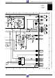
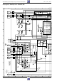
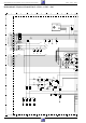
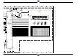
Bedieneinheit I / Keyboard Control Unit I – GV44…, GV45… (DC)
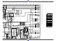
160-0011.1 (2L)
3
1
1
1
160-0011.1 (2L)
3
1
1
1
7010
110
1070
1516
1075
2015
5015
160-7011.1 (4B)
3112 403 3011.2
PCB CONTROL I
27507-607.31
1
1
55
FIP21001
361
*
428
+
1
2
14
13
1510
3068
3080
3083
3046
3060
3055
3045
3067
3065
3040
3058
7090
7088
7050
7080
7055
7045
7040
2018
2016
2010
2075
2068
2062
3084
3081
3088
3082
3090
3092
3043
3052
3042
3053
3050
3075
3062
6050
6040
2032
2030
2035
2033
2065
2021
2020
2023
16151413121110987654321
16151413121110987654321
A
B
C
D
A
B
C
D
16151413121110987654321
16151413121110987654321
A
B
C
D
A
B
C
D
8
2065 7A
2068 5 A
2075 3A
3040 5 A
3042 5A
3043 5 A
3045 5A
3046 8 B
3050 5A
3052 5 A
3053 5A
3055 6A
3058 6 A
3060 6A
3062 8 A
3065 7A
3067 4 A
3068 9A
3075 3 A
3080 7B
3081 14 B
3082 14 B
3083 14 A
3084 14 A
3088 8 B
3090 8B
3092 8 B
6040 4A
6050 4 A
7040 5A
7045 5 A
7050 5A
7055 5 A
7075 9B
7080 7 B
7088 7B
7090 8 B
$END
2010 15 A
2016 9 B
2018 8 A
2020 2 D
2021 7 A
2023 1 B
2030 5 B
2032 4 B
2033 4 B
2035 5 C
2062 8 A
74C
8 3D
94B
10 3 B
11 4 D
12 6 B
110 11 A
1070 10 A
1075 3 A
1510 2 A
1516 4 A
2015 3 B
5015 2B
7010 15 A
p07b31s3.PCB
12B
2 3C
31D
41C
51B
6 16 B
5
3
2
11
74
10
9
12
1
6
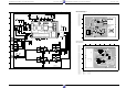
1510 –> Chassisplatte / Family Board
1516 –> Bedieneinheit II / Keyboard Control Unit II
Ansicht von der Bestückungsseite
View of the Components Side
Ansicht von der Lötseite
View of the Solder Side