
Computer Hardware User Manual

Allgemeiner Teil / General Section CUC 1806 / 1829 / 1830 / 1929
2 GRUNDIG Service
Es gelten die Vorschriften und Sicherheitshin-
weise gemäß dem Service Manual "Sicherheit",
Sach-Nummer 72010-800.00, sowie zusätzlich
die eventuell abweichenden, landesspezifischen
Vorschriften!
The regulations and safety instructions shall be
valid as provided by the "Safety" Service Manual,
part number 72010-800.00, as well as the
respective national deviations.
GB
D
For these TV sets the Service Manual CUC 1828 is applicable.
This Manual describes the differences and the additionally fitted
modules of the TV receivers.
The Module List and the relevant part numbers are listed in the table
on page 2.
Basic instructions for servicing are given in the:
– Safety Instructions (Part No. 72010-800.00)
– Service Manual CUC 1828 (Part No. 72010-021.10)
Table of Contents
Page
Module List ...................................................................................... 2
Technical Data ................................................................................ 3
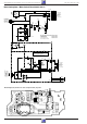
Mains Switch Board 29305-165.75 ................................................. 4
ControlUnit 29501-082.68 ............................................................... 5
ControlUnit 29501-082.67 ............................................................... 7
Keyboard 29501-083.02 ................................................................. 7
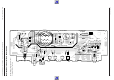
Mains Chassis ................................................................................. 9
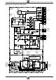
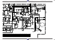
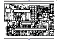
Colour Chassis .............................................................................. 13
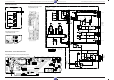
PIP Module 29524-106.54 ............................................................ 17
Active Aerial Crossover Network 29620-013.01/.02/.03 ............... 21
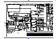
Signal Moeule 29504-102.34 ........................................................ 23
Spare Parts Lists ........................................................................... 27
Für diese Geräte gilt das Service Manual CUC 1828 (Digi Basic ++).
Diese Ergänzung dokumentiert die Unterschiede bzw. zusätzlichen
Bestückungen der Geräte.
Die Modulübersicht und die Sachnummern der einzelnen Bausteine
entnehmen Sie bitte der Tabelle auf Seite 2.
Grundlage für den Service sind:
– Sicherheitsvorschriften (Sach-Nr. 72010-800.00)
– Service Manual CUC 1828 (Sach-Nr. 72010-021.10)
Inhaltsverzeichnis
Seite
Modulübersicht ................................................................................ 2
Technische Daten ........................................................................... 3
Netzschalterplatte 29305-165.75 .................................................... 4
Bedieneinheit 29501-082.68 ........................................................... 5
Bedieneinheit 29501-082.67 ........................................................... 7
Keyboard 29501-083.02 ................................................................. 7
Netz-Chassis ................................................................................... 9
Color-Chassis ............................................................................... 13
PIP-Baustein 29524-106.54 .......................................................... 17
Aktive Antennenweiche 29620-013.01/.02/.03 ............................. 21
Signalbaustein 29504-102.34 ....................................................... 23
Ersatzteillisten ............................................................................... 27
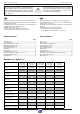
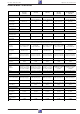
Modulübersicht / Module List
M 55-280/8 A
IDTV LOG
CUC 1806
M 72-100 A
CUC 1830
M 72-100 /8 A
CUC 1830
M 84-210/8 A
IDTV LOG
CUC 1829
Atlanta SE 7220 A
IDTV/PIP
CUC 1830
Bestell-Nr.
Order No.
G.CG 5175 G.CG 5475 G.CG 5375 G.CG 5590
G.CG 5224
G.CG 5275
Chassis 29701-096.56 29701-096.58 29701-096.57 29701-096.59 29701-096.60
Signal Baustein
Signal Module
29524-162.34 29524-102.34 29524-162.34 29524-162.34 29524-102.34
Tuner 29504-201.21 29504-201.21 29504-201.21 29504-201.21 29504-201.21
Bedieneinheit
Control Unit
29501-082.68
––
29501-082.67
–
Feature Box 29524-103.42 29524-103.42 29524-103.42 29524-103.42 29524-103.42
Bildrohrplatte
CRT Panel
29305-122.17 29305-122.17 29305-122.17 29305-122.17 29305-122.17
Buchsenplatte
Socket Board
–
29305-008.40 29305-008.40
–
29305-008.41
VGA-Buchsenplatte
VGA Socket Board
29305-160.36
––– –
Netzteil Standby
Mains Chassis Standby
29304-050.29 29304-050.29 29304-050.29 29304-050.29 29304-050.29
Netzschalterplatte
Main Switch Panel
–
29305-165.68 29305-165.68
–
29305-165.75
TP 800 29642-061.01 29642-061.01 29642-061.01 29642-061.01 29642-061.01
Keyboard
–
29501-083.24 29501-083.24
–
29501-083.02
Aktive Antennenweiche
Active Aerial Crossover Network
––––
29620-013.01/.02/.03